VFD Clocks
VFD-based tube clocks
- Details
$104 / kit (case not included)
Akafugu Corporation / akafugu.jp
Per Johan Groland sent me a nice little VFD clock for review and I think you’ll like this one.
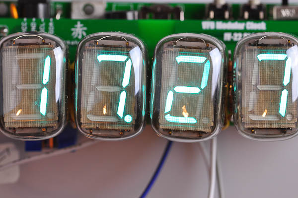
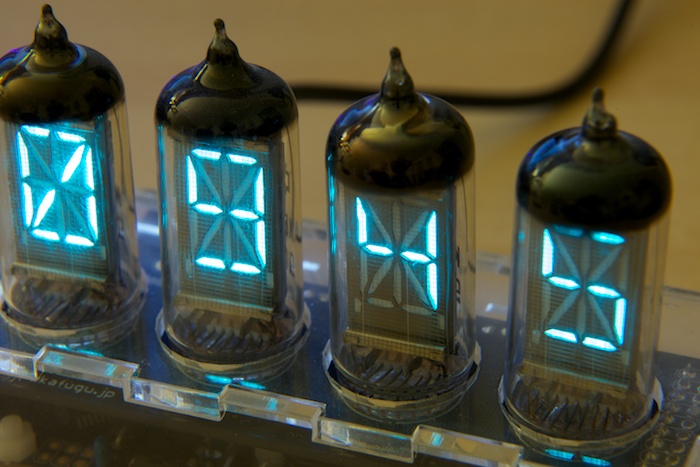
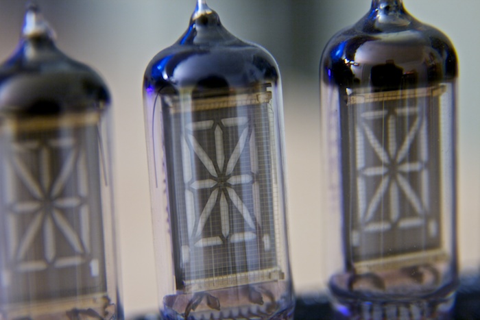
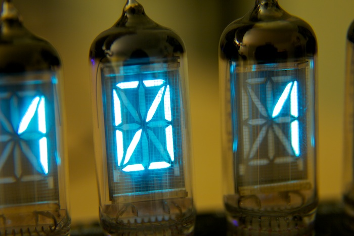
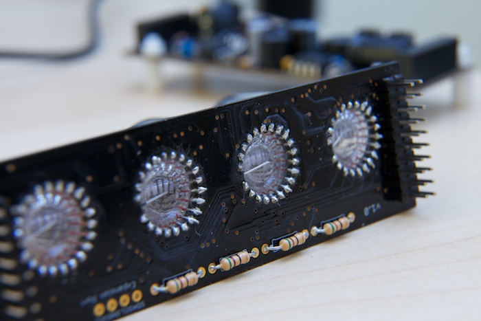
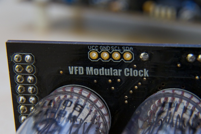
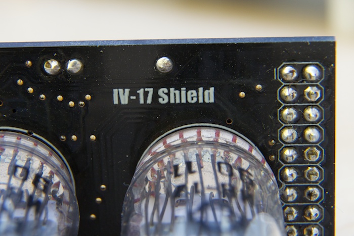
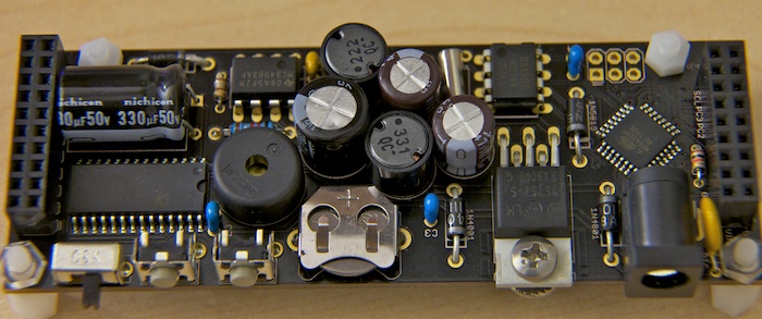
This clock is made up of four IV-17 alphanumeric VFD tubes. As it ships, the electronics come in two parts – the base with the microcontroller and the shield with the VFD tubes. The base can support up to four sixteen-segment tubes or twenty seven-segment displays.
The big draw to this board, in my opinion, is how hacker-friendly it is. The software is open source and available on GitHub. It ships with an ISP header for easy software upgrades. Given this combination, it makes a great platform for experimenting with. If you want to make your own four letter word machine or to experiment with VFD tubes, this is a great place to start.
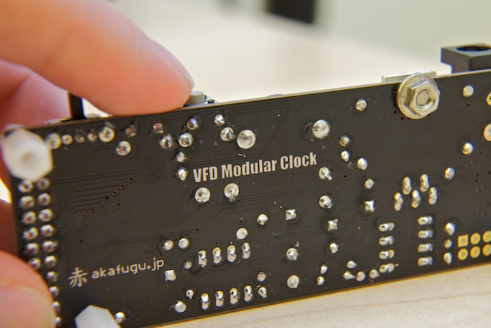
I received this device fully assembled but it normally ships as a kit. It looks relatively straightforward to assemble but I would estimate that each half of the device will take about an hour to do.
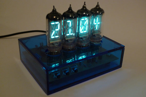
When the device is operating as a clock (using the shipping firmware) the operation is very straightforward. The clock can operate in 12h or 24h mode, the brightness can be adjusted, and there is also an alarm. Nearing the menu structure is pretty easy and there is a manual online to make setting the device easier.
The one feature that is missing from this firmware release is a display off time. Since VFD tubes wear out, it would be nice to have the display shutoff during certain hours of the day. This is not a major problem in my opinion given how easy it is to find VFD tubes on eBay, but it is something I wanted to point out.
The enclosure is a clear acrylic that has been cut in an almost jigsaw puzzle like fashion. This ensures that the pieces only fit together one way. Once assembled, I would suggest lightly tacking the base pieces together to prevent the sides or back from falling off. The electronics themselves are not actually attached to the enclosure.
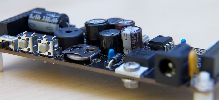
One of the features of this clock that I particularly like is it’s size – the entire device is one of the smallest that I’ve reviewed. This is partly because it is a four digit design but it also means that it is easier to find room for this gadget on a crowded desk.
Now, you’re probably thinking that this would make a great four letter word machine and you would be right. A FLW modification is in development to support this feature. It will actually require an extra EEPROM to support the dictionary needed for this device.
As of the time of this review, inly the IV-17 shield is available. There are three more shields in development: and IV-16, IV-22, and IV-18. These should be available shortly.
Overall – I’m a fan of this little device. The hacker-friendly nature of the gadget and it’s low price ($104 for the kit) mean that this will appeal to a wide audience. This is a great way to get started working with VFD’s without having to worry about the electrical engineering part. Be sure to look at the photos below to get a better idea of what is included and watch the review.
Alternate Shields
Currently, only the IV-17 shield is on sale. The IV-6 is almost ready for production and the IV-18 and IV-22 will need a little but more work before they go on sale.
Photos:
Links:
- Details
This clock swears at you.
Matt Evans has built a very nice four letter word machine based on an IV-17 VFD tubes that is worth checking out. It has a couple of neat features: it has an auto dimming display at night, it has a variable rudeness setting to control the dictionary used and it even has an alarm. Go check out his site and other project at his website: Axio.ms

Links
- Details
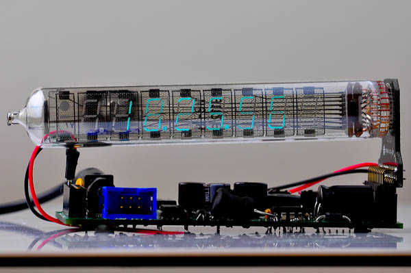
Okay, I've gotten my little hands on an IV-18 vfd clock from Turbo Mac. I've done a review of his single digit nixie clock before and it set the bar high for my expectations from him. This clock lives up to that. Watch the review below for more information. Also, be sure to check out his other items for sale on eBay - he has some cool gadgets. If you're looking for a holiday gift, take a look here :)
Video Review:
{vimeo width="700" height="390"}16912900{/vimeo}
Clock Settings:
Press SET to enter the setting menu.
Use SELECT to choose 1-6. Press SET to enter.
1 - Date (format: MM.DD.YYYY)
Press UP/DOWN to change the current (blinking) digit.
Press SELECT to jump to next digit.
Press SET to confirm and quit.
2 - Time (format: HH-MM-SS)
Press UP/DOWN to change the current (blinking) digit.
Press SELECT to jump to next digit.
Press SET to confirm and quit.
3 - Alarm 1 (format: HH-MM)
Press UP/DOWN to change the current (blinking) digit.
Press SELECT to jump to next digit.
Press SET to confirm and quit.
("24-00" will off this alarm.)
4 - Alarm 2 (format: HH-MM)
Press UP/DOWN to change the current (blinking) digit.
Press SELECT to jump to next digit.
Press SET to confirm and quit.
("24-00" will off this alarm.)
5 - Alarm 3 (format: HH-MM)
Press UP/DOWN to change the current (blinking) digit.
Press SELECT to jump to next digit.
Press SET to confirm and quit.
("24-00" will off this alarm.)
6 - Brightness (00: dimmest 07: brightest)
Press UP/DOWN to change the current (blinking) digit.
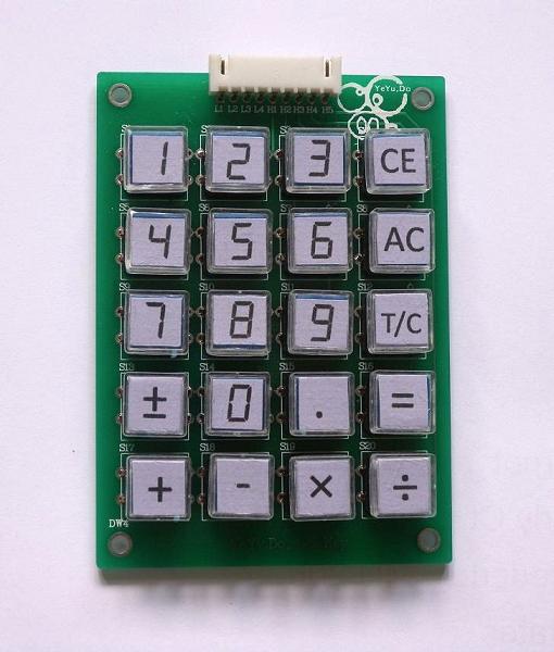
Optional Number Pad:
Links:
- Details
Price 159 €

Intro
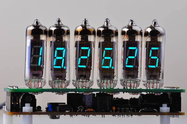
Jürgen Grau, the inventor behind the IN-12 Nixie clock I reviewed a few weeks ago, has a new clock kit on the market. This one is based off of six discreet IV-12 type vacuum fluorescent tubes.
The tubes are illuminated from underneath with RGB LEDs whose color, brightness, and cycling pattern can be changed with the push of a button. The enclosure is a professional Plexiglas design that gives the clock a more polished feel than any other VFD clock I have encountered.
One of the Facebook users commented that Jürgen’s IN-12 clock possessed a unique combination of hardware and software that made his Nixie clock stand out from other designs on the market. I fully agree with that statement and this applies to his IV-12 design.
The two second review: This clock is a winner.
Video Review
The Clock as a Whole
Before I start any review, I like to use the clock for a week, to play with its options and to see how it performs over time. After playing with this device for several days I discovered the one thing that really makes this clock stand out from the others on my desk: it is the vibrancy of the led base lighting.
Construction
The clock is composed of six layers (excluding the PCB), the top three of which are clear. The Plexiglas case allows for the vibrant colors to show through undiffused. This, paired with the nature of LEDs yields a surprisingly nice effect. My camera cannot accurately capture the colors produced by this clock. While the colors in the photos look fully saturated, the actual LEDs are much more vibrant in real life.
The case provides a solid and attractive foundation for the clock. The acyclic layers allow for viewers to see through to the PCB and to read the markings on the board and on the components. Every electronics fan likes to see what is inside a gadget and this design allows you to do that.
All of the buttons are on the top of the enclosure. The front three are used for setting the time, changing display characteristics and setting other functions. The button behind the tubes is used to turn the base lighting on and off as well as to set the display pattern.
LED Lighting
Each tube has a three color LED underneath it and the six LEDs cycle in unison. The clock comes programmed with fourteen color and brightness combinations to choose from. The pattern are set in bright/dim pairs with markers between them. For example:
Pattern A Bright, Pattern A Dim, Marker, Pattern B Bright, Pattern B Dim, Marker II, etc...
To cycle through the color patterns, simply double click the button behind the display. There are markings visible on the PCB if you forget which button this is. Additionally, on the back of the user manual is a chart showing the different patterns along with a brief tutorial on how to change the patterns.
There are a few other LEDs on the clock. There are two LEDs that act as as colons in the readout and one last that acts as an alarm indicator.


The Display
The display is based off of IV-12 tubes. I want to point out something important: these tubes are removable. (For more information on how VFD tubes work, refer to the bottom of this review.) They are almost identical to IV-11 tubes except that these have sockets.
There are other VFD tube clocks on the market that use IV-11 tubes but the major advantage of the socketed IV-12 tubes is that they are easily removable. This is a strong selling point for this kit. When a tube eventually breaks or wears out, it will be much easier to replace than if it were soldered to the board. Lastly, at the time of this review, IV-12 tubes can be purchased for a little over a dollar a piece.
The IV-12 tubes have a digit height of about 2 centimeters and glow a vibrant cyan color that is easily visible in bright daylight. The brightness is controlled via pulse width modulation and can be programmed to dim or shut off at night. (I generally recommend using this feature because prolongs the tube life.)
The digits fade smoothly between values. This clock offers 10 fade speed levels ranging from none (0) to fast (9). Generally, I prefer to use this effect at full brightness or not at all when dimmed. When dimmed, the effect causes a slight flicker in some of the segments.
Like on Jürgen’s IN-12 clock, this clock offers two transition effects. The first is a simulated slot machine effect where numbers are randomly shown and the “selected” digit is the correct value for that position. The second is a wave effect where numbers are moved back and forth across the display. On a nixie clock, these effects provide protection against cathode poisoning. On a VFD clock, they simply provide eye candy. (I prefer the slot machine effect.)
Lastly, the display offers a night time dimming mode. This allows the user to specify a time at which the display brightness dims or is turned off completely. This is set by menu options 13 and 14. 13 sets the time for the dimming to commence and 14 sets the duration of the dimming or display blanking. Option 12 is used to set the dimmed brightness from off (0) to full power (10).
As a Kit
As a kit, the assembly is pretty straight froward. As mentioned above, the estimated time to build this device is about three hours. All of the components are clearly labeled and grouped logically in plastic bags to ease assembly. Jürgen provides a nice color coded map of the PCB to allow for quick placement of the components.
Once the PCB is assembled, the other major remaining piece is to assemble the enclosure. The enclosure is made up of of 5 plastic pieces stacked on top of each other to build the enclosure. The top three layers a clear while the layers below the PCB are black. Assembling the enclosure is simple if you follow the steps in the manual.
While this may not be a beginners level kit, I feel confident that given enough time and patience, most people could correctly and safely assemble this kit. As the assembly manual says “Take it easy.”
The Manuals
Like on Jürgen’s IN-12 clock, the manuals on this device are great. They are divided in to the Owner’s Manual and the Assembly Manual.
The Owner’s Manual is twelve pages long (at the time of this writing) and features a clear, color coded layout to help you perform common tasks such as setting the time, changing the LED colors, etc. On the back of the manual is a simple diagram of the built in color schemes. All of the clock functions are clearly laid out in the manual and common use cases are presented. The simple menu structure on the clock and the clean manual layout make setting this clock a breeze!
The Assembly Manual details the steps for building the clock and provides helpful hints and photos to ensure a successful assembly. In addition to the text instructions, Jürgen includes numerous photos and diagrams to assist in assembly. The estimated time for assembly is about three hours.
Clock Options
- Time Display Format
- Leading Zero Suppression
- Digit Cross Fading
- Date Format
- Date Display
- Date Display Scrolling Speed
- Digit Cycling Mode
- Slot Stop Format
- Brightness of Standard Tube Display (daytime brightness)
- Clock Precision
- Alarm Tone Sound
- Dimmed Brightness (nighttime brightness)
- Start Time of Dimmed Brightness
- Duration of Dimmed Brightness
Included in the kit:
- All electronic parts + double sided PCB with dark blue solder mask and white silkscreen
- All VFD-tubes and socket pins
- All mechanical enclosure parts
- Universal power supply
- Printed assembly manual
- Printed user manual
- A tool for properly forming lead grid of the components
- A pair of fabric gloves to leave no fingerprints
- A spare tube IV-12
Photos

(Top of PCB)

(Bottom of PCB)

(Resistors)

(Diodes, including RGB LEDs)

(IV-12 Tube)

(The Kit)

(The Housing)

(Assembly hardware)

(Capacitors)

(Integrated Circuits)

(Tube Pins)
Verdict
I currently have several nixie clock, numitron clocks, and VFD clocks on my desk. Of all of them, this one draws the most attention from my guests.
Tehnical Data
- Tubes: IV-12 Nixie tubes socket type, 21 mm digit height
- Background lighting: Full RGB color spectrum with multiple display sequences
- Alarm: adjustable time, snooze and tone.
- Time format: 12- or 24 hour mode.
- Display: time / alarm / date / or alternating time - date.
- Effects: scrolling date, display fading, digit cycling in different styles.
- Power: 12VDC 650mA max.
- DC Power consumption: ca. 7VA (Full tube and LED brightness).
- Power Failure Backup Timekeeping: more than an hour with 1F SuperCap
- Time accuracy: internal 4 MHz crystal with user-adjustable precision settings
- Dimension (W x H x D): app. 196 x 23 x 65 mm (excl. tubes)
- Weight: app. 350 g
- Enclosure: Laser milled Plexiglas with sandwich layers
How VFD Tubes Work
The device consists of a hot cathode (filaments), anodes (phosphor) and grids encased in a glass envelope under a high vacuum condition. The cathode is made up of fine tungsten wires, coated by alkaline earth metal oxides, which emit electrons when heated by an electric current. These electrons are controlled and diffused by the grids, which are made up of thin metal. If electrons impinge on the phosphor-coated plates, they fluoresce, emitting light. Unlike the orange-glowing cathodes of traditional vacuum tubes, VFD cathodes are efficient emitters at much cooler temperatures, and are therefore essentially invisible.
The principle of operation is identical to that of a vacuum tube triode. Electrons can only reach (and "illuminate") a given plate element if both the grid and the plate are at a positive potential with respect to the cathode. This allows the displays to be organized as multiplexed displays where the multiple grids and plates form a matrix, minimizing the number of signal pins required. In the example of the VCR display shown to the right, the grids are arranged so that only one digit is illuminated at a time. All of the similar plates in all of the digits (for example, all of the lower-left plates in all of the digits) are connected in parallel. One by one, the microprocessor driving the display enables a digit by placing a positive voltage on that digit's grid and then placing a positive voltage on the appropriate plates. Electrons flow through that digit's grid and strike those plates that are at a positive potential. The microprocessor cycles through illuminating the digits in this way at a rate high enough to create the illusion of all digits glowing at once via persistence of vision. Several amateurs have experimented with the possibilities of using VFDs as triodes.
(From Wikipedia)
Links
Lastly, if you have any questions, post them in the comments and I will try to answer them for you!
Search