VFD Clocks
VFD-based tube clocks
- Details
General
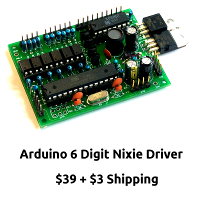
This is an IV-11 VFD clock kit, which I bought while I was looking around for a Vacuum Fluorescent Display clock kit. I was only half impressed by it. Most of all I was impressed by how fast it arrived, but not much else.
The Good
Well, it arrived really quickly. I was frankly shocked how quickly this kit arrived from China. Oh, we in the western world can only dream of a postal service as good as that which Hong Kong Post delivers, day after day, after day, after day, week after week, year after year. A box arrived two or three days after I ordered from the other side of the world. Wow!
Less than 3 days, here's the proof:
The bad
No real instructions. No help. You are on your own. Abandon hope all ye who enter here, lest ye be adept in the art of electrickery! Seriously, this kit is not for you unless you have constructed at least a couple of other clocks previously. There is no help available, and you really are on your own. You need to know how to use a meter and your head, and you'll be OK, in the end.
I'm not sure that the seller even really understands what he is selling. I have the suspicion that the whole kit might not be above board.
The Ugly
The candy shop LEDs certainly qualify as ugly in my book. It's like being stranded in Walt Disney's wet dream. There's no subtlety here. It's just... PURPLE, then GREEN then RED and then some BLUE. And BIG. However, I suppose we all need some more colour in our lives...
Links
- Details
Dmitry at Magictale Electronics recently sent me the Luminardo to review (well, not that recently any more, sorry Dmitry...), and it's a clock that is worth a closer look because of the time and effort that Dmitry put into creating it. It is clearly a labor of love, and ultimately that has been it's downfall.
Unfortunately, you can't buy one of these, because Dmitry is not selling them any more, because he just can't get the price down enough to make it an interesting proposition with a reasonable price. This is the last one.
The Luminardo is a small format VFD clock with bang up to date electronics, which is based on the Arduino, and really it is more of a device platform than a clock as such. The code is all in a GitHub repository, and it is all compatible with the normal Arduino IDE. There's even an Arduino compatible port on the back of the clock, so you can just plug the Luminardo in to your computer to flash new firmware on it right away. In the repository are also the hardware files, and the Luminardo is therefore an open hardware and open source project. Nice!
If making a board for the Luminardo is too much, you can just go over to Magictale's Tindy account and pick up the board. If you have a look on the Magictale site, there is an abundance of information and downloads there. Sometimes it is hard to find what you are looking for, because there is simply so much information there. It's a sort of Geek Ulysses, a huge stream of consciousness, a fire-hose of ideas from the clearly (over?) active mind of the creator.
The clock from the outside
I had to wait a long time to get my hands on one for review: it had to come from Australia, and it had to be built before sending it. When it came, it arrived in a small box, well packed and protected. Unwrapping it revealed a cute white package in a carefully designed 3D printed case:
The Luminardo is a long term personal project that Magictale has been pursuing for quite a while now. I quizzed Dmitry about the price that he would sell it for if he was going to sell it, but he explained that he couldn't get the production cost down enough to make it viable to sell it, because the cost in time and parts was just too high to make it something that is viable as a commercial product. I believe this without hesitation: The amount of work that has gone into this clock must be enormous. Apart from the 8 digit, 15 segment display, the clock literally bristles with sensors:
- The PIR detector on the top turns the clock on when you walk into the room
- There is a speaker in the left with a hole in the front panel to let the sound out
- Below that there is an LDR
- On the right there is an RGB LED
- and below that an IR sensor
Round the back, there is even more:
- On the left the is a temperature sensor
- Just above it there is a connector for an external sensor for outdoor temperature measurements
- Below that, a standard 6-pin ICSP port
- An exposed I2C connector
- A serial port 1
- A serial port 0 which is also used by onboard USB-to-serial converter
- A USB host interface with type 'A' receptacle
- A USB-to-serial interface with type 'B' mini receptacle
- On the side, a power barrel jack
- On top of the case there is a hole for accessing a reset micro switch.
From the inside
The assembly is made of two PCBs. Firstly a motherboard with CPU, peripherals and power source unit, and secondly a display module, the two are interconnected with a 14-pin header. The original idea was to make display panels interchangeable to take advantage different types of VFDs, with different number of digits/symbols and segments. The boards are detailed SMD boards, with a high density, and must be a trial to assemble.
The unit can be powered by a single power source, either through the power barrel jack on the side or through the mini USB connector. The relatively high and filament voltages needed by VFD are generated internally. The VFD power supply design doesn't have notorious shortcuts like powering filament with DC or using a software driven high voltage generator or using a charge pump which by its nature can't provide constant voltage level. Instead, a high voltage generator circuitry has a feedback and a pulse filament drive is used, eliminating typical issues like brightness gradient and dependency between brightness and total number of segments being lit. Still, the solution is simple, inexpensive and doesn't use custom made transformers.
As for the electronic components, the circuitry uses highly a available and extremely popular buck boost switching regulator MC34063 and a mono audio amplifier which are unlikely going to become obsolete in foreseeable future, and even if they do, they could be easily substituted with something else. The VFD glass is controlled by a specialised driver which does the multiplexing, controls dimming and has a convenient SPI-like serial interface, such driver is often used in modern DVD players. The VFD panel has a power down mode allowing significantly reduce power consumption and prolong VFD glass lifetime.
The heart of the motherboard is an ATMEGA with 128 Kb of program memory onboard making plenty of room for experimentations. The board has a battery backed dedicated real time clock chip which doesn't loose track of time even during power outages. It also provides 56 bytes battery backed RAM with unlimited number of read/write cycles which is very convenient for keeping user settings, for example, alarm time.There is also a conventional FTDI-based USB-to-Serial converter for flashing applications and serial debugging, just like a typical Arduino. Besides, there is a USB host functionality based on MAX3431E chip which has a mature software support by opensource library https://github.com/felis/USB_Host_Shield_2.0 evolved over the years. While the ATMEGA clearly doesn't have capabilities to work with web cameras it can easily handle such things as Bluethooth dongles or USB flash drives so it is really easy to turn the clock into a datalogger or control it by an Android phone. The board has two power rails, 5V and 3.3V with most of the logic and the micro using 3.3V. Both rails are available on an external expansion header along with the SPI interface theoretically making a provision for a third board-shield in between the two boards, however, the current design of the case doesn't accommodate for it.
The case is also a little work of art. It's clearly 3D printed, but has curves and recesses, bezels and details that tell you someone spent a long time on it. The PIR sensor on the top of the unit is half hidden and does not call attention to itself. Even though the PIR sensor is recessed, it still has a wide field of view, and the clock wakes up before you are fully in the room.
The remote control
One really nice feature is the software controlled remote control unit. When the clock starts up, it prompts you to set up the remote control by displaying "RCSETUP" if the Infra-red sensor detects any signal during this time, it goes into "learn" mode.
This means you can use pretty much any remote control you have laying around, and teach the clock the buttons you will be using. Gone are the days when losing the remote control was a big problem. That's a really nice feature!
Programming the Luminardo
With a totally normal USB cable you can link up the Luminardo to you Arduino IDE, and after you install a hardware definition file into the IDE, the Luminardo appears in the IDE as a device in the "Tools > Boards" menu. You can make changes to the code and upload it in a matter of seconds. This makes the development cycle with the Luminardo very direct and quick. Have an idea, code it, upload it, test it all in a few seconds.
Conclusion
It's a lovely little clock, and it's a real shame that it is over-engineered to the point of being impossible to mass produce. I mean this in terms that to be able to market a product with this level of sophistication, the price is going to have to be well up in the $250+ range. I paid $150 for mine, which was the review price, therefore basically cost price. By the time that support, returns profit and administration, fees, shipping and all the rest of the costs of production are factored in, the price will certainly end up at least double the cost, so around $300.
It is a shame. This is a really neat little clock, but unfortunately, it does not have a future at the moment, primarily because it is over-specified and over-engineered.
Links
- Details
Intro
I discovered this wonderful tiny VFD clock by chance, while browsing Tindie for novelties. As I’m a newcomer to this Nixie/VFD world, I was not aware that Brian Stuckey already did an article in 2014 on a previous incarnation of this clock (Akafugu Modular VFD Clock).
I contacted Per Johan Groland, owner of the Japanese maker Akafugu that makes these clocks, for all the shields I could get my hands on - The only shield I did not order was the 4 tube IN-4/17 shield, which Brian already tested and which I find does not do this clock justice.
The VFD Modular clock arrived as a kit. Shipping from Japan to Switzerland took less than two weeks. All the parts are well packed, each in its own bag. The PCBs have a glossy black solder mask with golden ENIG finish.
A USB cable is also included. The main PCB is protected in its own bag. You can order the tubes from Akafugu. If you have already ordered tubes from elsewhere, like eBay, it’s also possible to order the clock without tubes. This clock can be ordered in Akafugu’s own shop, Tindie or eBay. For custom orders, like ordering several or only specific shields, it’s preferable to contact Akafugu via email. It’s also possible to order acrylic cases.
Per also shipped the 6 tube IV-4/17, the IV-18, the IV-22 and the IV-6 shields. I did not order a case, as I intend in the future to make my own. At the risk of repeating some of what Brian already said, I'll perform a full review of all the shields except the one that was already reviewed. It's important that this review be self contained and that you don't have to make reference to previous articles.
The clock has two parts - the clock base board and the tube shields.
Base board
The base board size is just 100x35mm big. It uses 10mm nylon spacers so the PCB does not sit directly on the surface.
On both left and right sides of the board there are two pin headers - this is where the shields will connect to.
There are two buttons, confusingly labelled S1 and S2, where S1 is “Button 2” and S2 is “Button 1” on the back side of the PCB. There’s also a two-position switch that enables or disables the alarm. This is an interesting point - where one can control the alarm with a switch instead of entering menus to enable/disable it. This is a lot quicker and easier than fiddling around in menus, especially if you are sleepy.
On shields that support dots, the alarm enabled indicator is shown as the rightmost dot or a big dot (IV-18 shield).
Also on the backside there’s a USB mini connector - you can use this connector to power the clock, as well to program it. On the front of the board there are two LEDs - one blinks when your power-on the board - and the other blinks when the board is being programmed.
There’s additionally a SMT switch that resets the clock.
Underneath the clock there’s a row of pins compatible with Adafruit’s GPS module. Any GPS or GPS emulator, like nwts, should work with this clock, if connecting at TTL levels and if supporting 4800 or 9600 bps. The clock uses the $GPRMC NMEA string to get its time. It will synchronize the time every 1 minute. The clock supplies 5V to power the GPS module.
The main components of the base board are:
- ATmega32U4RC: 32K bytes 8 bit MCU with ISP flash and USB controller
- DS3231: Extremely Accurate I²C-Integrated RTC/TCXO/Crystal
- MAX 1771: Step up DC-DC controller
- 24LC512: 512Kb (64KB) EEPROM
- HV5812: 20 channel VFD display driver
There’s also a description of an I²C temperature/humidity sensor on the clock’s schematics, but this is not included in the board. Currently the clock derives its temperature from the RTC chip – but as the clock warms up a bit, this temperature is always a few degrees higher. Measuring with a laser temperature sensor, the temperature reported matches the RTC surface temperature.
The ATmega is preloaded with an Arduino Leonardo bootloader – this allows programing the open source firmware using just a USB cable and the Arduino IDE. Also included are ICSP pads on the underside of the board, but these require a pogo-pin adapter to be able to use them.
This probably the clock’s greatest strength: it’s completely open source. The current firmware code is published on GitHub.
Finally, there’s a 3.3V CR1220 battery holder to allow the RTC to maintain the current time in case the clock gets disconnected from power.
The shields
The following shields are available:
- 4 tube IV-4/IV-17 shield
- 6 tube IV-4/IV-17 shield
- 6 tube IV-6 shield
- 1 tube 8 digit IV-18 shield
- 6 tube IV-22 shield
A really nice touch is that the clock detects what shield is connected by a 3-bit pattern and adapts itself to show the correct display for the different tubes, there is no need to set any thing up for the different shields.
Every shield has a hole for each tube, with grooves for each tube’s wire contacts. Before soldering the tube, extending the wires outward and placing them in the grooves, allows for an easy alignment and soldering. It also makes it possible to replace a tube easily.
The IV-22 shield uses expensive Harwin tube sockets, the same as used in other clock models from other manufacturers - this allows an even easier replacement of the tubes.
The IV-6 and IV-22 tube shields are very similar on their display capabilities - the only difference being the size and orientation. The clock operates very similar with these tubes.
The IV-18 shield has two additional digits, making use the two additional digits for longer scroll and FLW animations. Also uses the big dot on those tubes as an alarm indicator.
The IV-4/IV-17 shields use the tube’s sixteen-segment display to display real letters; on the seven segment tubes, we can only guess what letter is shown, on the sixteen-segment tubes this works out very well. However, due to the additional segments, disappointingly, this module does not have any dots.
All the shields except the IV-18 have additional I2C pins that allow future expansion!
Usage
Starting the clock for the first time, the Load LED will pulse for about 8 seconds, after that the display will show which shield is loaded.
The clock will then display the time/date/temperature/four letter words/message on the display, depending on the configured parameters.
The menu system is simple and efficient, but takes some time to get used to.
Button 1 advances to the next menu item. Button 2 changes that item value. If a menu item ends with a dash, this means there’s a sub-menu. Pressing Button 2 enters that sub-menu and again Button 1 moves to the next item and Button 2 changes that menu value. It can take some time to get used to it, or to try to decipher the characters on the seven-segment displays.
The full menu I could derive from the source code is:
|
Menu/Param |
SubMenu 1 |
SubMenu 2 |
Values |
Description |
|
|
24H |
|
|
ON/OFF |
24/12 hour display |
|
|
ADATE |
|
|
ON/OFF |
Show date |
|
|
|
REGN |
|
DMY/MDY/YMD |
Regional date format |
|
|
ADIM |
|
|
ON/OFF |
Automatic display dim |
|
|
|
ADH1 |
|
2 |
Period 1 |
Start hour |
|
|
ADL1 |
|
8 |
Intensity |
|
|
|
ADH2 |
|
19 |
Period 2 |
Start hour |
|
|
ADL2 |
|
5 |
Intensity |
|
|
|
ADH3 |
|
22 |
Period 3 |
Start hour |
|
|
ADL3 |
|
2 |
Intensity |
|
|
ALARM |
|
|
|
|
|
|
|
HOUR |
|
0 |
Alarm hour |
|
|
|
MIN |
|
0 |
Alarm minutes |
|
|
BRIT |
|
|
0-10 |
Display brightness (will be overwritten by ADIM) |
|
|
DATE |
|
|
|
(Will be overwritten if using GPS) |
|
|
|
YEAR |
|
|
Current year |
|
|
|
MONTH |
|
|
Current month |
|
|
|
DAY |
|
|
Current day |
|
|
DOTS |
|
|
ON/OFF |
Display dots on hour separator |
|
|
DST |
|
|
AUTO/ON/OFF |
Enable DST (Auto will use default US values) |
|
|
|
RULES |
|
|
|
|
|
|
|
RULE0 |
3 |
DST Start |
Month |
|
|
|
RULE1 |
1 |
DOW |
|
|
|
|
RULE2 |
2 |
DOW Occurrence |
|
|
|
|
RULE3 |
2 |
Hour |
|
|
|
|
RULE4 |
11 |
DST End |
Month |
|
|
|
RULE5 |
1 |
DOW |
|
|
|
|
RULE6 |
1 |
DOW Occurrence |
|
|
|
|
RULE7 |
2 |
Hour |
|
|
|
|
RULE8 |
1 |
Offset (hour) |
|
|
FLW |
|
|
ON/OFF/FULL |
Four Letter Word (FULL is uncensored) |
|
|
HUMI |
|
|
ON/OFF |
Humidity |
|
|
PRES |
|
|
ON/OFF |
Pressure |
|
|
GPS |
|
|
OFF/48/96 |
GPS Baud rate |
|
|
|
TZH |
|
-12 to 12 |
GPS Time zone hours difference from UTC |
|
|
|
THM |
|
0-59 |
GPS Time zone minutes difference from UTC |
|
|
|
GPSC |
|
ON/OFF |
GPS CKS errors debug |
|
|
|
GPST |
|
ON/OFF |
GPS Parse errors debug |
|
|
|
GPSP |
|
ON/OFF |
GPS Time errors debug |
|
|
TEMP |
|
|
ON/OFF |
Show temperature |
|
|
TIME |
|
|
|
(Will be overwritten if using GPS) |
|
|
|
HOUR |
|
0-23 |
Current hour |
|
|
|
MIN |
|
0-59 |
Current minutes |
|
|
VOL |
|
|
LO/HI |
Buzzer volume |
|
Toggling the alarm switch enables or disables the alarm. On all shields except the IV-4/IV-17shields there’s a dot that indicates the alarm is on.
The clock supports 12/24 hours, day/month/year, month/day/year and year/month/day formats.
The display can also be dimmed – automatic dim times can also be defined.
Also, another good option is to set DST rules – though it might get a little bit tricky to master.
The alarm volume can also be changed.
GPS settings are the normal ones we can find on other clocks, like setting the baud-rate, GMT hour and minute difference and some GPS debug options to troubleshoot GPS problems.
Firmware customization
Exploring the code, some interesting things can be found:
- Define messages for specific dates: Special messages that will be triggered on a certain date can be coded into the software
- Control LEDs via I2C
- Use a rotary encoder
- Use additional temperature, atmospheric pressure or humidity sensors
To compile the code, it requires the necessary WireRTC control library, that’s also available in the standard Arduino distribution. The code shows many available options and it’s quite big, but it seems easy to read and understand.
Some of the extra options, like the pressure and humidity are undocumented, only existing on the source code – no wiring or parts are described on the documentation. Presumably these are for future expansion.
What was not so good
Before my final thoughts, I’d like to point out that there are some areas that require some improvement.
The documentation on the site, though mostly complete, requires some clean-up and the removal of some ambiguities, like references to parts that don’t exist anymore. It’s clear that improvements are being added both to the hardware and the software and those are not reflected in documentation, making it sometimes a little bit frustrating. Akafugu acknowledged those problems and is currently fixing them up. Some of the clean-up is already in place when this review was published.
One of the main “faults” I’d like to point out is a missing complete table that includes all the menus of the device and a matrix with each shield features. I’m sure this would help many buyers deciding.
Another page that requires some cleaning is the Resources page. A clear place where to find schematics, manuals and links to the software would be something that would make the experience less frustrating. Though the clock schematic is available, I couldn’t find the shields schematics - they might be important when troubleshooting tube problems, because the way each shield is driven is considerably different from the others.
On the clock software, I’ve noticed that some features work sporadically, like the Four-Letter Word display – sometimes the tubes are just blank. I’m not sure if this is an issue of a specific shield, but usually a restart of the clock solves this issue. Akafugu suggested to check if the EEPROM chip connections or adding a decoupling cap, but since I started this review, the problem did not happen again.
Final thoughts
The device is very well made – it clear that it has already some years of development and fine-tuning. The fact that the source code is available, makes this device very desirable for hacking, customization and general learning on how to make a Nixie or a VFD clock.
Assembling the kit is relatively easy once some of the ambiguities of the documentation are solved. The hole with groves method of assembling wire tubes is very useful!
It’s a pretty device and an excellent use of several VFD tubes.
Communication with Akafugu has always been excellent – Per Johan Groland has been very communicative and ready to help with any questions asked.
I’d recommend this device for all those that like VFDs, a small beautiful clock or a piece of hardware you can also hack and play with. It sure is one of my favourite VFD clocks so far!
Links
- Details
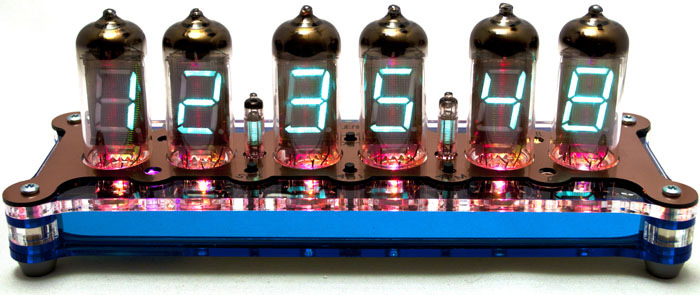
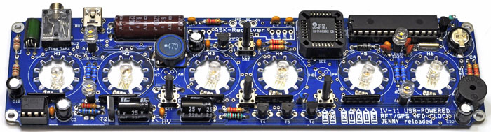
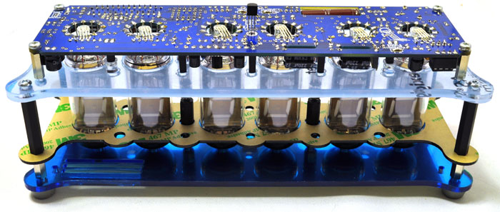
One of my all time favorite VFD clocks is the Jenny design from NixieKits.eu. Well, Jürgen Grau has a new version out that is USB powered and is based on the same firmware as the Lena/Lars/Laura clocks. This thing looks awesome.
Features
- Hours, Minutes and Seconds display
- 3 x 2 multiplex for less tube noise and higher brightness; based on the modern Supertex HV driver HV5812
- Selectable 12 or 24 hour display modes
- Uses a Quartz Crystal Oscillator as timebase with software adjustable accuracy
- Programmable leading zero blanking
- Date display in either DD.MM.YY or MM.DD.YY or YY.MM.DD format
- Programmable date display each minute or selectable with a single button push
- Scrolling display during fading-in the date or standard display change
- Alarm with programmable snooze period
- Optional DCF / WWVB / MSF / GPS sync. with status LED; prepared for fitting the ASK receiver module from the „Wireless GPS connection“
- Dedicated DST button for easy switching between DST and standard time
- Super Capacitor backup keeps time during power outages for more than 6 hours.
- Simple time setting using two buttons
- Five programmable IV-15 column settings (Flashing AM/PM indication, illuminated AM/PM indication, always flashing, always on / off)
- Seconds can be reset to zero to precisely set the time
- Programmable night mode - blanked or dimmed display to save tubes life or prevent sleep disturbance
- Indicator LEDs dim at night mode too to prevent sleep disturbance
- Weekday aware „Master Blank“ function to turn off all displays on weekends or working hours
- Separate modes for column IV-15 tubes during night mode
- Standard or fading display modes as an eye-catcher
- „Slot Machine“ effect as eye-catcher
- Programmable RGB tube lighting – select your favourite colour palette
- 729 colours possible. Have a different colour of your choice every hour or autochanging colours with variable speed
- Programmable temperature display in °C or °F at seconds 30...35
- All user preferences stored in non-volatile memory
- Circuity works with safe 36 VDC Tubes Anode voltage
Links
Search