After a confusing start, (entirely self inflicted complications caused by not just simply doing what the instructions said) the Scope Clock is nearing completion. The final steps went really fast, in fact much easier than expected, and after only a few minutes, it was clear that we are on the right path.
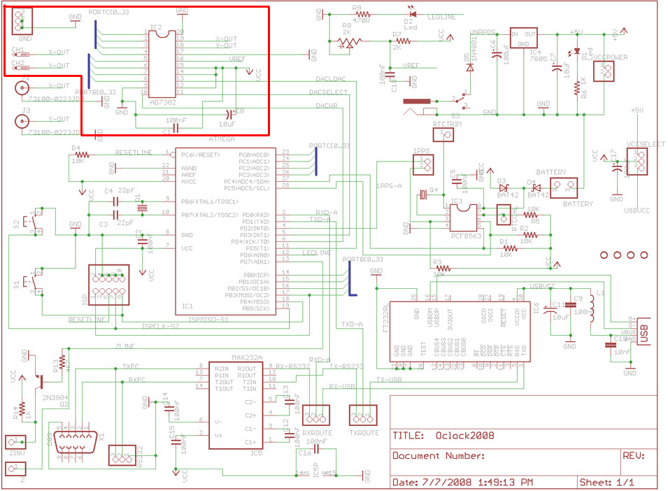
Putting on the DAC

At this point, the temptation was simply too great. Even though I only have one lead made up and could only look at a single channel, I just had to have a look what the scope was doing. In the video you can see what it looked like. It was of course totally unreadable, but staring at the pattern for a few seconds, it became clear that something good was going on.
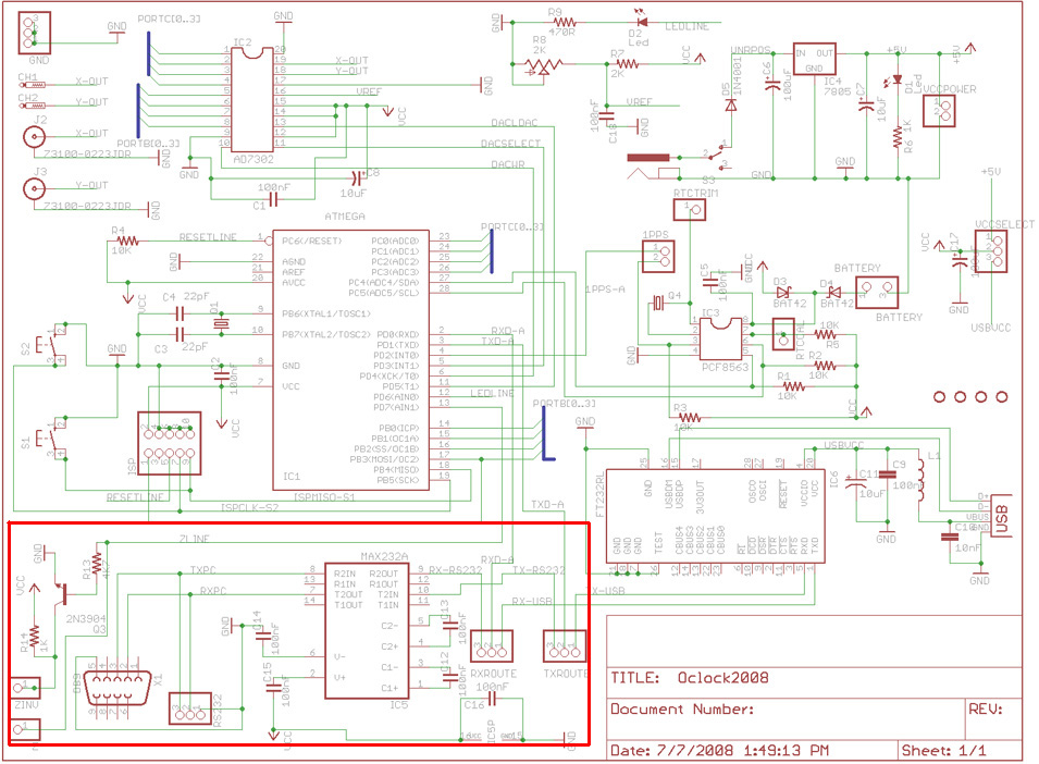
Some RS232 with that?

To complete the build, the RS232 chip (a HIN232ACP, a new one to me) was added and the chunky D-Type socket.
Giving it a first try
After all that, plugging the board into the scope with both channels immediately gave a picture that was recognizable. It was turned on it's side and back to front, but it was clearly a clock face. Switching the X and Y axis and turning off a channel invert made the clock face appear correctly.
How cool is that?
Video wrap-up

