Recently a Dutchtronix Oscilloscope clock module arrived by post, and it seems a really nice kit. Oscilloscope (or just "Scope") clocks have a fairly limited appeal, but the people they appeal to really, really like them. They are, in all seriousness, the pinnacle of geekness.
Q1: Who has a scope?
A1: A geek.
Q2: Who has a scope clock?
A2: A cool geek.
This article takes us through the first part of the build of the clock.
Before starting, it's worth looking at the information that is available on the Dutchtronix web site, and there is a LOT of it up there. This is a well documented kit, with all of the technical information that you might want. There are schematics, a parts list (even though the kit comes with all the parts you'll need), fairly detailed assembly instructions and even source code (but for a previous version, V4.0). The current software (V4.2) is only available as a pre-compiled binary file.
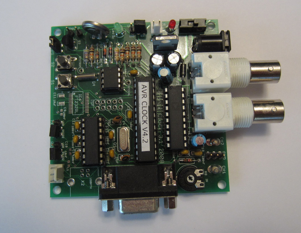
The circuit board itself looks well made and well laid out. I notice that this design is not new - it appears to date from 2008, as is written on the board. This is clearly a tried and tested design, but even though the circuit does not seem to have been updated recently, the design still seems to be thoroughly relevant and quite up to date; All of the components are currently and easily available, and are none look to be old or outdated generation components.
One possible trap for people who are inexperienced: There is a ground plane on the back of the board, and the "isolation" (the distance between the component pads and the ground plane) is very fine. If you are not that experienced with soldering, or are using a tip on your soldering iron that is too big, you risk making short circuits which are difficult to locate. The problem can come if you "dig" at a connection with the soldering iron, and remove some of the solder mask from around the pins (it's quite easily done if you are not careful, the solder mask is quite fragile). When you come to solder the pin, tiny whiskers of solder can form between the pin and the ground plane. It would be a valid modification to increase the width of the isolation, or at least make a note in the assembly instructions that make people aware of this risk. If you are careful, it will not be a problem, but you have to be careful.
Preparing for the Build
 I checked the packaging, and all of the components were there as listed in the parts list. The contents of the kit is impressive for the price. I paid $35 for it, including shipping to Europe. (In the US, it is $30). The costs of the connectors alone is a significant part of the price. The assembly instructions suggest more or less throwing the components onto the board in order of lowest profile to highest profile components. A preferable way is to build the circuit in logical stages, and perform a check after each stage. This helps you discover problems early, and know that something in the last portion of the build went wrong. This in turn drastically cuts down problem solving time, and as an added benefit ensures that you don't destroy more components than absolutely necessary.
The first part of the build was therefore to get a feeling of what to build first from the schematics.
I decided to tackle the build in these stages:
The power supply
The controller
The RTC (Real Time Clock)
The reference voltage for the DACs (Digital to Analogue Coverters)
The DAC [Next episode]
The RS232 interface, and finally [Next episode]
The connectors and any sundries ("sundries" = bits that are still on the bench at the end = Things I forgot earlier, hmmmm) [Next episode]
Building the Power Supply
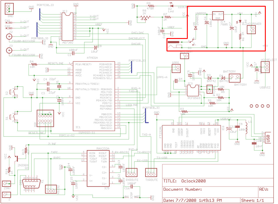 Logically, the first step seemed to be to build the power supply. This is shown outlined in red in the picture. This is a simple and straightforward linear regulator circuit built on the venerable 7805 linear regulator. Nothing could go wrong with this, right?
I put in the components, and checked before powering it up that things were in the right orientation. Turning the power on, I was expecting the red LED to come on, but... nothing!
Going back the schematic, it became clear that the small "on/off" switch close to the barrel jack was missing. Adding that still didn't make the light come on. This time the "VCCSELECT" jumper was missing. This is used to select between external power and USB power.
Now it worked!
Putting the controller on the board
 Next, it seemed logical to put the controller and the supporting components on the board, and see if we can get any action on the data pins on the controller. This would prove that the controller is alive and well. The components I imagine are needed are shown in the red box. These are the standard set of components for powering up an Atmega328.
After installing the components, I was expecting the green LED to do something, but nothing happened at all. Pressing the buttons didn't change anything. I got out the oscillosope and probed the Atmega pins, to no avail. The controller had flatlined.
I wrote to Jan de Rie, and he answered quite quickly, given the time zone difference, but the answer wasn't that helpful. He said that the controller should start up when power is applied, but it didn't. I got out my home built Atmel programmer and read out the flash memory to check that something had been installed on the controller. It looked the same as the binary image available from the site. Moreover, the controller responded perfectly to the programmer, so there was clearly something else wrong.
One one of the FAQs there was a note that to put the controller into program mode, you need to hold down the switch S1 while powering on. I did this and the green LED started to flash, so it appeared that the controller circuit was just fine, but it was missing something to make the controller run.
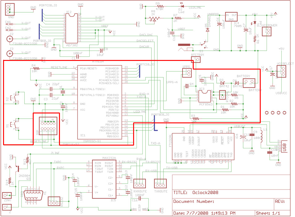 I stared at the schematic for another while, and spotted one thing that might be important. The controller is driven by the RTC module via a "1PPS" (1 Pulse Per Second) connection, as well as an I2C connection. What if the controller needs the I2C or the 1PPS in order to start up?
The RTC circuit
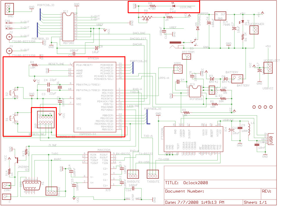
Given that the controller was working (it flashed the green LED when you start the board in "flash" mode), I added the rest of the components in the extended red box, and then... IT WORKED! The Green LED flashed merrily!
The DAC reference voltage circuit
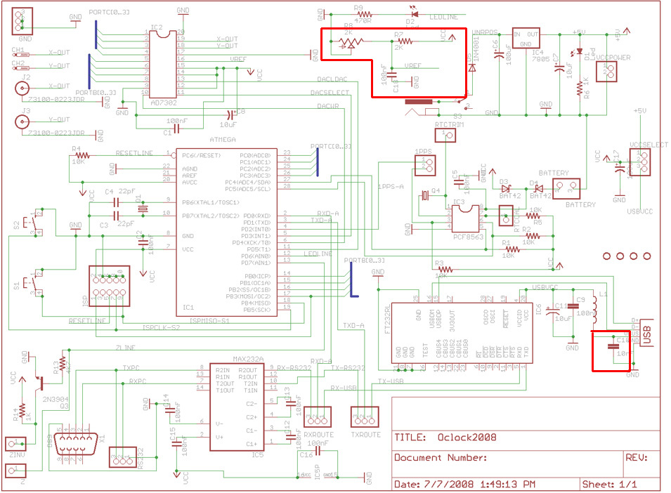 This circuit allows you to change the size of the image that is displayed on the scope. This is a really simple piece of circuitry to build, and I only had one problem: There was no 2k resistor in the parts I received, so I made one by putting two 1k resistors in series. I didn't notice that there was a resistor missing.
Next Episode
In the next part, we'll finish the build.
Video wrap-up