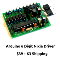
You get what you pay for!
That's the lasting impression when working with this clock. It's not very cheap, but there seems to be no corner cut, or compromise made. It's worth every penny you paid, and you'll end up thinking it's probably worth more than you paid.
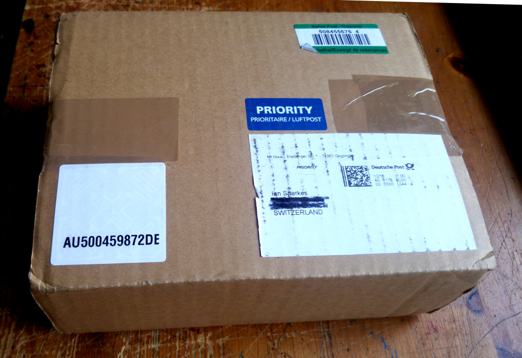 From the moment of receiving the box (you have to sign for it, it is sent via tracked post), the impression is good. "That's a big box" for a clock kit, but when you open it up, all the surprise of receiving such a big box dissolves. The box is big because it contains lots, and it's beautifully packed, well padded and full of electronic and retro goodies. One thing to note is that the IV-13 Numitron tubes are not included in the kit I received, and you'll have to shop around for them.
A power supply is provided, with the appropriate plug for the county the package is sent to. That's a nice touch, and shows that care and attention has gone into every aspect of the clock presentation. The power supply is not some cheap no name brand. It's heavy, chunky and clearly a quality unit, with certifications on the rear side. The difference between this supply and some other supplies is that the certifications are real.
Inside the box
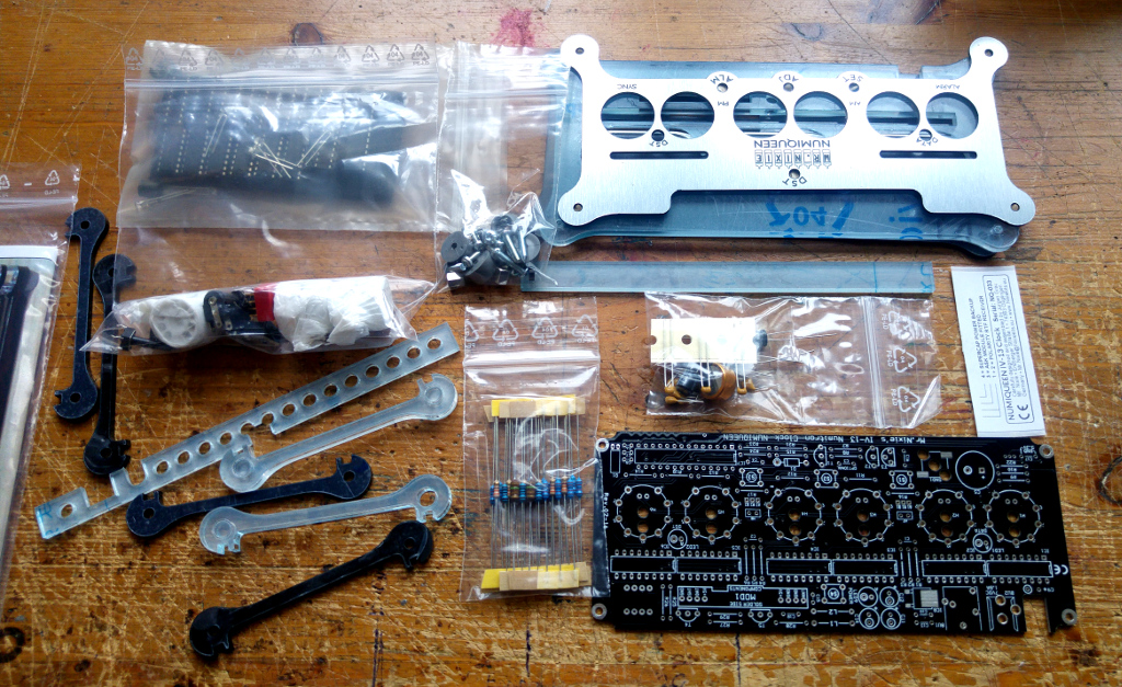 The impression of quality remains when you open up the box. There is a case included in the kit, and it looks nicely made, and includes all of the hardware needed, right down to the rubber feet. All the ICs are provided with sockets, as well as ceramic sockets for the tubes.
The number of components is not particularly high, and while the instructions say that this is a kit build for the experienced electronics enthusiast, the level of skill needed does not seem all that high. Nearly all of the components are "through hole" (which means they are easier to handle and mount for the average hobbyist, because they don't need special tools. There are two large format surface mount devices, but neither these are a problem to mount without special tools. Tweezers help, but are by no means an absolute necessity.
The Assembly Manual
The instruction manual is available online and this is an area that could do with a little more explanation for clock constructors without much experience. To be fair, Jürgen does aim this kit at people with a fair level of experience, but addition of a few more words in the manual would lower the experience bar a good deal. The assembly instructions are correct, but a little short in places. If you have plenty of experience, you will sail through the assembly, but if you are quite new to constructing clocks, you might find it a little confusing or vague in places. If you can read the schematic, you'll be just fine.
Performing the assembly
As with all things in life, it's best to have a plan and stick to it. In this case, the plan is formed by knowing a little bit of what you are doing, which in turn means read the schematic and understand what the various parts of the circuit are for.
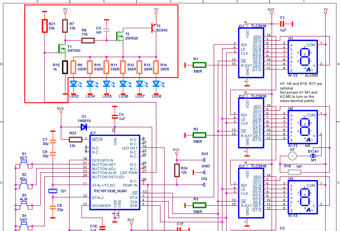
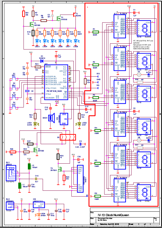
The schematic for the NumiQueen is not particularly large or complicated, and it breaks down into the following parts:
The power supply
The controller circuit, buttons and speaker
The LED driver
The tube drivers
The tubes
The case
We'll tackle each of these in turn.
The power supply
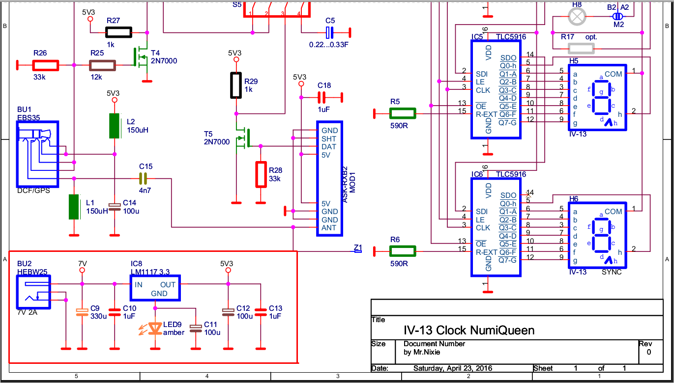 The power supply is a fairly normal linear LDO (Low Drop Out) regulator based on the LM1117. Interestingly, the regulator uses a 3.3V regulator, along with an LED to "push" the ground of the regulator up to around +2V, this gives an effective regulated output voltage of 5.3V.
The power supply is made up of IC8, BU2, C9, C10, LED9, C11, C12 and C13. the capacitor C9 is mounted on the board in a cut out to reduce the profile of the board.
Putting these on the board only takes a few minutes, and powering the unit up gave us a nice amber light. The voltages measure within range, so we are good, A tip when installing IC8 is to put a small blob of solder on one of the pins, then align the chip with just this one pin soldered. When it is aligned how you want, solder the other connections.
The controller circuit, buttons and speaker
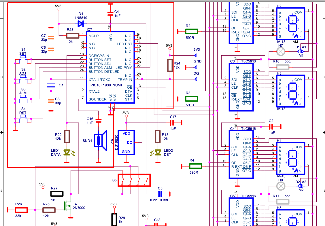 Next up is the controller, plus the supporting components so we are able to see and/or hear that the controller is working. This circuit gives us the oscillator for the controller plus the switches and the speaker, as well as a resistor to enable the controller and some decoupling. With these components, I hope to hear the controller peep when I press buttons, which will prove that the controller is alive. The components we are installing here are IC7, S1-4, Q1, C6-8, R22-24, C4, C16, D1, LED1 and SND1.
Put the socket for IC7 on the board with just one or two pins, then solder the rest when it is aligned how you want.
After putting these components on the board, we hear beeping from the speaker, so we are good.
The LED driver circuit
 I wanted to build the whole LED circuit in one go, but I was not sure exactly how the LEDs should be mounted. The manual was not very clear about this. I noticed that the holes on the board were large enough that the LEDs passed through them without trouble. Also the sockets seemed to have a hole in the center with just the right size for the LED head to fit in it. I made the guess that it would be best to fit the LEDs later. I did the rest of the circuitry, but did not mount the LEDs just yet.
The LED driver is made up of some control circuitry to allow the LEDs to be switched on and off (T1-3, R7, R8, R15, R21), current limiting resistors (R9.14) and the LEDs themselves (LED3.8).
I wasn't able to test this yet, so moved on.
The Tube Drivers and tubes
 All of the clever stuff for the tube driver circuit goes on in IC1-6, meaning that the circuitry for the tube driver circuit is deceptively simple. The only slightly tricky part of this part of the build is mounting the tube sockets, which are really easy to get skewed. I started by soldering one pin of each socket, and checking that they were seated properly. Once they looked good, I soldered the opposite pin of each socket and checked the alignment again. Once I was happy, I soldered all the remaining pins.
I fired up the clock with just one tube installed, and it worked great!
After this, I installed the other tubes and checked that they worked! Yaaay!
LED backlights part 2
Now that the tube sockets were installed, I out the LEDs into place. Now it was clear that they go though the board (the center hole) and up into the sockets. The pins are bent over to allow contact with the pads on the PCB. I soldered them in, and they worked.
Other components
There were some other components to install for the DIP switch and the time sources, so I put these on, following the markings on the PCB. I did mis-read one of the resistor values, so had to carefully remove it and move it. The only component which does not go on the board yet is the temperature sensor IC9. This is mounted during the case assembly.
The Case
The case is also quite easy to construct. The instructions are quite clear, and the hardest part of the construction is to peel off the protecting film from the panels without scratching anything. At the end, the result looks great.
Don't forget to mount the temperature sensor so that it just pokes out of the case.
Closing thoughts
This is a great kit, and requires a moderate level of skill to assemble it. The result is fantastic, and the IV-13 tubes are bright and clear. There are not many "gotchas" in the build, and if you pay attention and take your time, things will be fine. Only one thing was a little tricky from a soldering perspective: The solder pads of the controller are very fine, and took more attention than all other the other components. It was not hard, just needed more care.
Would I recommend this kit? I can say a resounding "yes".
It's easily one of the most satisfying clocks I have made, and the build rewards you quickly and fairly easily. Any easier and it would not feel like an achievement, any harder and you would be frustrated. It meets the right balance. A particularly satisfying moment is being able to put the clock in an attractive case at the end of the build, dust your hands off and really say "I'm done".
Total build time was about 3 hours, with no profanity. So it must have been good.
{youtube}LAiAPCak554{/youtube}