Uncategorised
- Details
Originally from:
https://forum.elektrolab.eu/threads/navod-na-vyrobu-digitronu.36/
I have translated and archived this, just in case anyone needs it.
Introduction
Gradually I will update here in parts and over time how to produce a Nixie tube. Everything will be explained, from materials used, material cleaning, production of functional vacuum sealing, assembling, shaping and welding of glass, scoring metal parts, pumping and vacuum measurement, leak check in glass, degassing of the Nixie and glass system, noble gas filling, gettering, equipment, where to buy individual components and many other things.
First, the necessary equipment will be described, followed by a list of materials, and finally the entire technical process, including all important parts will be described.
The entire manual will be a comprehensive set of information that you need to know if someone chooses to produce digitrons. You will not find this information with a complete explanation on the Internet together and I believe that this thread will find its followers. If this thread had existed two years ago, I myself would use it for my project, it would make it easier for me to solve many of the problems encountered in Nixie manufacturing and glass work.
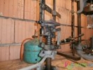
Part 1: * Vacuum pump station, noble gas filling method and adapter for vacuum-tight connection of the Nixie pump tube.
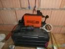
For the production of Nixies, it is first necessary to obtain a vacuum pumping apparatus. To do this, the rotating oil two-stage vacuum pump, which is able to draw to 0.0001mbar is needed. All D-series vacuum pumps from Trivac meet such parameters. I use the Trivac D4B, the pumping speed is 4.200 liters per hour and the limit pressure without the suction on is 0.0001mbar, the turbomolecular or diffusion pump as the next stage is not needed. Only use oil recommended by the pump manufacturer, oil with a vapor pressure of 0.0001mbar or less.
Next you need 1 bellows shut-off valve for vacuum pump outlet, 1 bellows shut-off valve for filling the Nixie bulb with noble gas, orientation mechanical vacuum gauge at least -1bar, vacuum pipe with KF flange. The Trivac D4B has a KF16 output.
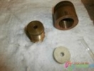
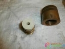
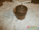
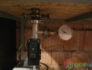
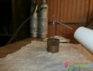
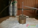
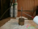
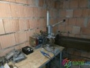
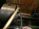
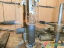
Finally, it is necessary to produce an adapter for the end of the KF pipe that will be used to connect the Nixie pump tube. It is designed as a basic bottom with an external thread and a hole with a diameter of 7 mm in the length of 20 mm and a hole of 5 mm continuing into the vacuum pipe. The step from 7mm to 5mm is to prevent the pipe from being sucked and moved into the vacuum pipe due to under pressure. On the basic bottom part is inserted a gasket with a hole in the axis with a diameter of 7mm (I use a SIMAX 3.3 pump tube with an outside diameter of 7mm with a wall thickness of 2mm), which I cast from N1522 lukoprene. After screwing on the upper part with internal thread, inserting the pump tube and tightening the upper part, the gasket is pressed, which will tightly wrap around the vacuum tube and seal the pump tube.
Below the filling adapter there is a filling part with a needle valve, the needle valve in my case is functional and tight, but it will be replaced by a bellows valve. The Cu capillary leads from the valve and is connected to the valve of the noble gas pressure vessel (Neon, Argon). The main shut-off valve at the outlet of the pump is fitted with an electric bellows flap valve with additional mechanical control (it will also be replaced by a bellows valve).
Photo documentation of the connection adapter and the overall solution of the vacuum piping and valves is attached below.
Links to accessories and bellows valves are here:
Bellows vacuum valves
KF pipe page, including all necessary items
https://www.aliexpress.com/wholesale?catId=0&initiative_id=SB_20200104032410&SearchText=kf+16
Mechanical vacuum gauge -1bar
http://www.ekotez.cz/vakuometr-01000-mbar18-npt-vg1000-p-2060.html
- Plavec-Part1_1
- Author: No Data
- Hits: 1663
- Downloads: 575
- Rating: No Votes
- Plavec-Part1_2
- Author: No Data
- Hits: 1805
- Downloads: 545
- Rating: No Votes
- Plavec-Part1_3
- Author: No Data
- Hits: 1603
- Downloads: 553
- Rating: 5.00 (1 Vote)
- Plavec-Part1_4
- Author: No Data
- Hits: 1605
- Downloads: 525
- Rating: No Votes
Part 2 * Cooling furnace and glass tension control.
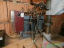
For the production of digitrons, another important component is the cooling furnace.
Each time the glass is treated with a flame, the treated preform must be placed in the furnace to cool, if not, the preform will burst upon cooling in the air, or it will burst at the next heat-up operation. Such an uncooled preform can unexpectedly spill over a million fragments all around.
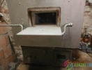
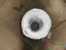
As a cooling furnace I personally use muffle furnace (photo attached below), which is on single-phase power supply 230V, fuse 16A and reaches a temperature of 1000 degrees Celsius. I added digital temperature measurement and digital control programmable controller (photo is attached below), which allows setting several types of cooling curves.
For SIMAX 3,3 glassware, the manufacturer recommends the following cooling procedure: The hot semi-finished product (after processing has approximately 500 ° C) is placed in a preheated oven at a temperature of at least 500 ° C. Then, the pre-set program is started, which heats the furnace to approx. 560 ° C and a controlled hold for approx. 20 minutes at this temperature, which completely heats the glass and releases the tension, just before the SIMAX glass collapse. . After the cooling the room is cooled to room temperature, the cooling time is given by the SIMAX glass producer and my furnace, which has a long cooling time, no longer heats the furnace during the cooling process. temperature I already remove the semi-finished product from the furnace and allow it to cool freely in the room in the air. From a temperature of 560 ° C after the endurance, it is important that the fall to 440 ° C is not faster than 14 ° C in 1 minute. From 440 ° C up to room temperature, a maximum drop of 140 ° C per minute is allowed, these parts are valid for 3mm glass thickness.
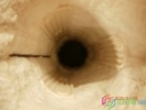
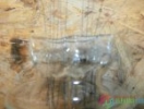
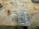
Polaroscope is used to check the tension in the glass. It is an expensive device that investigates stress in transparent materials (glass, plastic). Polaroscope can be cheaply replaced by a linear polarizing foil that can be placed in front of the PC monitor screen on which the white background is lit. An example of a linear polarizing film is here: http://www.tridakt.cz/3dshop/index.php?route=product/product&product_id=91
The polarizing foil is rotated in front of the monitor so that its surface is black-opaque, an object to be examined is inserted between the foil and the monitor to show whether there is a dangerous strain in the object. If there is no tension in the object, hereinafter referred to as in the glass, the structure is the same everywhere in appearance and without white spots. If there is tension in the glass, it is beautiful to see a spotty white structure at the stress point, as opposed to stress-free places. Photos of examples of glass examination in the attachment. One photo shows the stress at the top of the end of the pump tube-white spots. The second photo shows the blank for the production of vacuum sealing, the blank is completely stress-free.
- Plavec-Part2_1
- Author: No Data
- Hits: 1621
- Downloads: 542
- Rating: No Votes
- Plavec-Part2_2
- Author: No Data
- Hits: 1622
- Downloads: 542
- Rating: 5.00 (1 Vote)

- Plavec-Part2_3
- Author: No Data
- Hits: 1615
- Downloads: 521
- Rating: No Votes

- Plavec-Part2_4
- Author: No Data
- Hits: 1593
- Downloads: 551
- Rating: 1.00 (1 Vote)
Part 3 * Vacuum measurement, weld and melt test in glass.
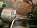
In the manufacturing practice of digitrons and vacuum tubes, the vacuum has never been measured and is not measured today and it is unnecessary to measure and detect it accurately. To detect the vacuum in this production application is sufficient classical mechanical vacuum gauge, which will show us immediate pressure reduction and vacuum pump function (reference to this vacuum gauge inserted in the 1st part) and further to determine the perfect exhaustion is used HV transformer, hereinafter referred to as PRSKAVKA.
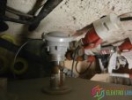
After placing the sparkler on the pumped flask, a discharge appears in the flask. At atmospheric pressure about 1013 mbar glow discharge is not present (air is insulator and the shock does not start), at the beginning of pumping is then first present red-violet discharge (pressure approx. 0.13 mbar), this discharge then changes to violet discharge (pressure approx. 01 mbar) and green glass fluorescence and glow discharge in the flask (pressure approx. 0.0013 mbar). This vacuum detection is absolutely sufficient during production, no expensive electronic vacuum gauges and other measuring methods are needed. Further pumping of the Trivac D4B vacuum pump achieves an even lower pressure to about 0.0001 mbar, further reduction by another order is achieved by a getter, but this will be discussed in another work.
The sparkler also tests the perfection of welds in glass and the quality of vacuum sealing. After applying the sparkler to the test site, the sparks of the discharge, if all is well, spread out over the glass surface. If there is any, even a microscopic leak, the sparkler discharges into this location, indicating a bad weld or leak. The sparkler must not be tested for more than a few seconds at one point, otherwise the glass will break through and cause leakage.
An example of where to buy this sparkler is here: https://www.aliexpress.com/item/32871173897.html?spm=a2g0s.9042311.0.0.37814c4d1Gjr0n
Photographs of sparklers in operation during vacuum detection here:
The third photo shows a vacuum of about 0.0013 mbar.
- Plavec-Part3_1
- Author: No Data
- Hits: 1550
- Downloads: 528
- Rating: No Votes
- Plavec-Part3_2
- Author: No Data
- Hits: 1512
- Downloads: 518
- Rating: No Votes
- Plavec-Part3_3
- Author: No Data
- Hits: 1511
- Downloads: 541
- Rating: 5.00 (1 Vote)
Part 4 * Gas welding kit.
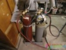
A powerful gas set is required for glass shaping, vacuum sealing and glass-bulb welding, as SIMAX glass has a higher processing temperature and higher flame performance requirements than soft glass. I have long struggled with this problem and searched for a suitable and especially cheap and affordable solution. I rejected special glass burners because of their high price and because of their high consumption of PB gas and mainly oxygen. I risked and bought into my personal property in Germany two 20 liter cylinders of acetylene and two 20 liter cylinders of oxygen, for which I bought regulators, hoses, handles, burners and protective elements with non-return valve and sintered sintered liner.
After the experiments I found out that it was a good choice and that this equipment was well suited to my intention.
I only use three sizes of classic oxy-fuel burners to work with glass:
* Burner 1-2 (for melting digitron pump tube from vacuum adapter)
* Torch 2-4 (for sinking the blanks blank on the lathe)
* Torch 6-9 (for welding a glass socket with a flask and for vacuum sealing). When welding a glass socket with a flask, I use an additional flame. A 3kg PB bomb and an injector burner with air intake are used. An additional burner is needed to gradually preheat the entire flask due to tension-adjusted to about half the power, and also serves as an auxiliary and significant source of heat when welding the flask to the socket — it is already set to maximum power. He already requires a very large heat source for this operation, because the flask has a wall thickness of 2.2 mm and the base is also made of glass 2.2 mm thick and in total it is a pretty solid, which must perfectly heat and weld. After welding, turn off the autogen and set the auxiliary burner to half power again, and then cool the whole to about 400 degrees Celsius in the glass to leave no stress, after this operation digitron I do not cool in the furnace, oxidize the internal stainless steel system and oxidation in vacuum was lengthy. After this operation, when the digitron is still hot (about 400 degrees Celsius), it goes to the pump immediately, as it would be a shame not to use this residual heat in the subsequent degassing process and not to save some of the energy for running the plug-in baking furnace. But I have already turned off the topic and this operation will be described in another episode. The welding of the flask base to the vertical rotating jig will also be described in another section.
For glass forming and welding, I basically use a reducing flame (for the ignorant - this is a flame with an excess of acetylene).
Neutral or oxidizing flame cannot be applied to glass, neutral flame does not heat the glass over a large area and the oxidizing flame foams and distorts the glass.
I change gas in Germany in exchange of an empty bottle for a full one while you wait. In the Czech Republic this is not possible, it is necessary to rent pressure vessels and to conclude a disadvantageous contract. I have described the whole issue of purchasing and collecting technical gases on my website and I will not discuss it here.
The link is here: http://nixieproducer.com/index.php/autogen-and-free-floor-full
- Plavec-Part4_1
- Author: No Data
- Hits: 1472
- Downloads: 547
- Rating: 5.00 (1 Vote)
- Plavec-Part4_2
- Author: No Data
- Hits: 1433
- Downloads: 532
- Rating: No Votes
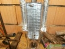
Part 5 * Plug-in baking oven.
Another important component in the production of digitrons and in the manufacture of vacuum tubes in general is the absolute necessity of baking, where glass and the stainless steel internal digitron system are degassed.
A suitable oven is required for this. In practice, this is accomplished by closing the set of vacuum tubes or digitrons connected to the manifold of the vacuum pumping apparatus with a heating chamber. I draw one piece at a time, so I chose a simple plug-in furnace.
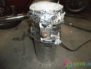
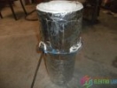
My furnace is made of stainless steel chimney tube with a diameter of 180 mm and a wall thickness of 1 mm. In the furnace I installed 3 pieces of plate heaters with a total output of 3x400W / 230V, the maximum allowable temperature on 1 lamp is 750 ° C. Body dimensions are 245x60 mm. The furnace is insulated with heat-resistant ceramic wool (resistance up to 1000 ° C) with a thickness of 20 mm from both sides. The furnace is fitted with a mechanical capillary thermostat with a range up to 450 ° C. The furnace as a whole is placed on a digitron, the top is covered with a refractory ceramic cotton wool and the heating is switched on, the temperature and the heating time will be described in another part, describing the complete procedure and theory of digitron production.
The reference to the specific heating elements used is here:
https://www.nadeta.cz/en/placement-details/other-heating-body/heating-the-body-table/zaric-tutles-400w-glaze-245x60mm-ceramic-deck-infrazaric - [id = 400190014] .html? ItemIdx = 582
- Plavec-Part5_1
- Author: No Data
- Hits: 1291
- Downloads: 545
- Rating: No Votes
- Plavec-Part5_2
- Author: No Data
- Hits: 1304
- Downloads: 548
- Rating: No Votes
- Plavec-Part5_3
- Author: No Data
- Hits: 1305
- Downloads: 541
- Rating: No Votes
- Plavec-Part5_4
- Author: No Data
- Hits: 1250
- Downloads: 520
- Rating: No Votes
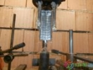
part 6 * Vacuum sealing device and glass base welding device with glass flask.
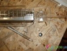
Vacuum sealing is a separate production chapter which will be described in detail in another part. For its repeatable production, however, it is necessary to own a suitable product that will facilitate work. It can be solved differently, manually by means of pliers, but it is inconvenient and of poor quality, the wires start and are not centered.
For this purpose, I made a rotating jig that has thrust jaws operated via a lever.
I was inspired by the YouTube video to make this product, the link is here, starting from 2 minutes and 25 seconds:
In the video you can see the start-up oven, which I wrote about in the 5th part, in the video it starts from time 4 minutes and 5 seconds.
I use exactly the same principle, the tungsten wires are inserted into the jig, the socket bore and the pump tube are choked, the jig is driven by a motor from the wipers of an unknown car and is powered by an adjustable source so I can set the required speed.
Another part of the production is welding of a glass base with a glass bulb. This operation can be solved by a glass lathe, which provides extensive application in digitron production. Unfortunately, I do not own a glass lathe (I plan to buy it over time) and so I was forced to make some jigs to perform this operation. I was again inspired by the video on YouTube where they use this medicine, it is in the same link I mentioned above. It starts from 3 minutes.
It is a vertical parallel rotating jig that works absolutely reliably. It is also driven by a motor from the wipers of an unknown car and powered by an adjustable source. The product contains a smoothing mechanism to smooth the heated glass. The pump tube and tungsten wires are hidden from the flame heat in the lower metal tube, which rotates in parallel with the upper clamping part. I solved the top part so that it can be moved sideways, in the video the top part moves up and down. This is due to the installation of the flask. I put the flask on the bottom part of the jig and on the top I move the digitron sideways with the handle and clamp the flask into the jaws. After welding, the procedure is reversed.
Photos of both products are attached here.
- Plavec-Part6_1
- Author: No Data
- Hits: 1335
- Downloads: 556
- Rating: 5.00 (1 Vote)
- Plavec-Part6_2
- Author: No Data
- Hits: 1301
- Downloads: 533
- Rating: No Votes
- Plavec-Part6_3
- Author: No Data
- Hits: 1367
- Downloads: 557
- Rating: No Votes
- Plavec-Part6_4
- Author: No Data
- Hits: 1335
- Downloads: 531
- Rating: No Votes
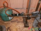
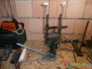
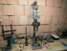
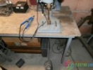
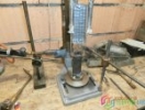
Part 7 * Spot-resistance welding machine.
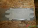
Another important and indispensable aid in the production of digitrons and vacuum tubes is the spot welder. This is used to score stainless steel sheets and tungsten lead wires for the stainless terminals of numerals.
Buying a spot welder is an expensive affair, so I went my own production. In the collection I found a three-phase transformer with parameters, primary 3x400V / secondary 24V / 6000VA. Secondary winding was solved by Cu strip conductor of rectangular cross-section of 50mm2. Unfortunately, the transformer was mechanically and freshly damaged the primary coil on the middle column of the core, was cut through the front with a sharp object, the transformer was apparently damaged during handling in the collection and was handed over to the collection functional. So I disassembled the transformer and unwound the entire secondary and completely removed the central coil. Newly I wound a new secondary using the original Cu strip conductor, while winding the secondary I used two strip Cu conductors in parallel on top of each other. For each coil (2 outer coils, middle column is free) I wound 4 coils of the secondary, I folded the transformer and connected the primary and secondary coils. As a result, the transformer is powered by two phases, so the power supply is 400V. The secondary output voltage is 4.8V and about 1250A.
After this work came the production of timer and transformer control. I did not use any SSR relay and I switch the transformer using a timer via a pedal using a contactor. The output of the timer is solved by means of an open-collector transistor and switches a 12V DC power contactor against the ground. The timer is operated by a pedal.
Finally, I thought for a long time how to solve the mechanical part of the welder, I thought of using a drill stand so I started to work. The mechanical part is handled by a manual lever thrust, which is coupled in the hollow beam of the foot thrust stand, so both methods of thrust can be used.
Micromode pliers are another accessory of the welding machine. I solved it with the grounding tongs on the welder. But I used the reverse way of controlling the pliers. The pliers are closed in the idle mode-electrodes together, this solution is suitable for my purposes, because when scoring tungsten on the stainless steel system I put the pliers and do not squeeze anything, the pliers due to the spring have a constant downforce. It is a convenient and simple solution. Production cost of spot welding machine (material only) was minimal and I fit in the amount of 1000, - Czech crowns, I had a drill stand, I bought only a contactor and hooker, the rest is from domestic supplies, transformer cost me 100, - Czech crowns.
Electrodes are made of special alloy CuCrZr, it is an alloy directly intended for electrodes of spot welders, it is not possible to use classic pure copper, copper is soft and does not last long, I bought it here:
https://prosvareni.cz/en-category_1058- 0-cucrzr-bars-to-spikes.html
The attached photos are beautiful to see the overall mechanical solution of my spot welder, further description is not needed, it is a simple and original solution, which is reliably functional. Welder welds two stainless steel sheets with a thickness of 4mm without any problems. I have uploaded a video of traffic and welding demonstrations of various materials on YouTube, but I have already deleted it.
- Plavec-Part7_1
- Author: No Data
- Hits: 1546
- Downloads: 520
- Rating: No Votes
- Plavec-Part7_2
- Author: No Data
- Hits: 1565
- Downloads: 545
- Rating: 5.00 (1 Vote)
- Plavec-Part7_3
- Author: No Data
- Hits: 1595
- Downloads: 548
- Rating: No Votes
- Plavec-Part7_4
- Author: No Data
- Hits: 1537
- Downloads: 544
- Rating: No Votes
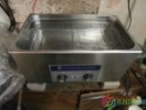
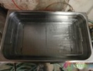
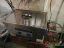
Part 8 * Ultrasonic Purifier and Filter for the Production of Dejonized Water-Reverse Osmosis.
In the production of digitrons it is necessary to thoroughly clean the individual components. An ultrasonic cleaner will serve this purpose well, a complete description of the cleaning process will be described in another section. I have a model with a bath volume of 22 l, ultrasonic power is 480 W, is equipped with 6 vibratory converters, ultrasonic frequency is 40 kHz, power is single-phase voltage 230 V, fuse 10 A, purifier has integrated bath tub heating with thermostat. Integrated heating is necessary, the efficiency of the purifier is highest at about 50 degrees Celsius.
I bought the purifier here-see below in the link, the menu currently have a new model with buttons and display, I have an old model with rotary display. The Chinese ship it from the EU warehouse, so you do not pay any CLO or VAT.
www.aliexpress.com
US $ 485.12 36% OFF | Skymen 22L 480W Ultrasonic Cleaner Heated DEGAS Semiwave Ultrasound Bath Solution Ultra Sonic Cleaning Device | Ultrasonic Cleaner Bath | Ultrasonic Cleaner | Ultrasonic Cleaner - AliExpress
Better Living! Aliexpress.com
www.aliexpress.com www.aliexpress.com
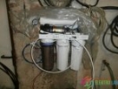
Another part is a device for the production of deionized water, it is a false alternative to distilled water, because the water is not distilled. They offer distilled water in gasoline and shop sales, but this is a consumer deception, and the water claimed to be distilled is not actually distilled and is produced using reverse osmosis. Distilled water would cost a lot more money because its production is energy intensive. Dejonized water, however, has parameters almost comparable to distilled water, it is free of all minerals and has minimal and almost zero conductivity. For the cleaning of digitron parts, this water is a necessity, generally it is hungry water, which extracts all impurities from the cleaned parts. My reverse osmosis filter also contains a conductivity meter, a water conductivity meter.
In my case, when supplying the filter with its own water from a well, I have a water conductivity of around 220 uS / cm at the inlet and a conductivity value of 0 to 2 uS / cm at the filter outlet.
I bought the reverse osmosis filter here: http://www.reverzni-osmozy.cz/2013/4-stupnove-jednotky-ro-410-a12
It is necessary to select a model with conductometer and rinsing valve, I recommend to configure the unit for the membrane with the highest flow rate, the output will have a higher flow rate and water production will be faster. RO50 membrane is fitted as standard and I recommend to install RO100 membrane in the device. The flushing valve is important, after the water production is finished, it rinses the membrane and thus extends its service life, more is written in the filter user manual. Furthermore, after purchasing the filter, it is necessary to check the correct connection of the conductometer, the conductometer has two probes, one connected to the inlet pipe and the other to the outlet pipe. I had a wiring error from the factory, the input probe was connected to the output of the middle filter and the conductometer still showed almost the same value as the output. At first I thought I had distilled water in the well, but after checking it, I found out that there was a mistake in the wiring. Fortunately, the prop tubes are long enough and there was no need to buy any. I disconnected the inlet probe of the conductometer from the connected point and installed it on the inlet pipe. Apparently someone wrongly involved in production when assembling the assembly, but I did not claim it, it would be delay. The photo of my filter is below.
- Plavec-Part8_1
- Author: No Data
- Hits: 1299
- Downloads: 532
- Rating: No Votes
- Plavec-Part8_2
- Author: No Data
- Hits: 1286
- Downloads: 529
- Rating: No Votes
- Plavec-Part8_3
- Author: No Data
- Hits: 1260
- Downloads: 524
- Rating: No Votes
- Plavec-Part8_4
- Author: No Data
- Hits: 1342
- Downloads: 617
- Rating: No Votes
part 9 * induction heating of the stainless steel digitron system and induction heating of the getter.
Another important production step in digitron production is the method of heating-activation of getter and heating of the stainless steel digitron system. This operation is essential, without the internal system being heated, degassing of the stainless steel will not take place.
For the purpose of heating the stainless steel system, I purchased a mid-frequency induction heating type DAWELL DHI-15. It is a single-phase induction heating operating in the frequency range of 20 to 60 kHz, the output gives 1.5kw. The frequency is controlled automatically by the processor and uses series resonance. However, the heating is not cooled by water, after overloading it goes into a rest state and after cooling it works again. Induction coils are made of Cu solid wire with a cross-section of 16mm2. I only use this heating to heat the internal digitron system. I made a coil according to the size of the flask, I pass it under vacuum under the flask and heat the internal system to red, which will evaporate the oxides and degassing. Photos below.
Induction heating is also needed to heat the getter, but at a much higher operating frequency, laser heating can also be used, but this is an unbearable costly thing I have rejected. Dawell DHI-15 can not handle this operation, has a very low operating frequency and can not heat up miniature components and nonferrous metals. Even if a special focusing coil is used, the getter cannot be heated to the required temperature and time via the getter.
For this purpose I was forced to buy another induction heating. It is heating with operating frequency up to 1,2MHz. The heating is completely water-cooled. I will not give further description of this heating here, this heating, photos and purchase link I have completely described and stated in this thread: -kw.28 / (request link check)
End of the 9th part (this is the end of a series of parts of the necessary equipment, in the next parts will be a list of the necessary materials and the production process of digitron)
- Plavec-Part9_1
- Author: No Data
- Hits: 739
- Downloads: 528
- Rating: No Votes
Part 10 * Materials for digitron production.
Purchase materials and references used in the JP47 digitron.
* Flask * tube SIMAX 3,3 pr.75mm / 2,2mm / 250mm
* Foot-seal * SIMAX 3.3 tube 40mm / 2mm / 55mm
* Pumping tube * SIMAX 3.3 tube.7mm / 1.5mm / 1500mm
(flasks are on request, otherwise tubes are in stock and shipped by the carrier, personal collection of tubes is not necessary as elsewhere): www.glass-sphere.com
* Anode lattice * AISI 304 stainless steel welded mesh 11,7mmx117,7mm / 1mm
www.alumat.cz
* Spacer * Flat washer DIN 125A M3 / 3,2 A2 Stainless steel
www.proprumysl.cz
* Centering insulator of cathodes from carrier wire * beads MATUBO size 8/0
* Cathode separator * Matubo Wheel 6 mm beads
www.koralkykomponenty.cz
* Pin Terminals * DT Series Pin Contact 0460-202-16141 Stainless Steel Male
https://www.aliexpress.com/item/10-20Pcs-DT-Series-Pin-Contact-0462-201-16141-0460-202-16141-Stainless-Steel-16-20AWG/32843591206.html?spm= a2g0s.9042311.0.0.3f064c4dqqyal0
* Anode cage and cathode holders * Stainless steel sheet 0.4mm AISI 304 2000x1000mm
www.inerez.cz
* Cathode-numbers, cathode insulator beams * AISI 304 0.9mm soft wire
www.anebotak.cz
* Wire for vacuum sealing * Tungsten wire diameter 0.3-0.35mm clean, polished
https://www.aliexpress.com/item/10-meter-Air-purifier-special-tungsten-wire-silver-white-black-99-9-high-purity-electrostatic-precipitator/32967234893.html?spm= 2114.search0204.3.2.675f62cdH1H88o & ws_ab_test = searchweb0_0, searchweb201602_6_10065_10068_319_317_10696_10084_453_10083_454_10618_10304_10307_10820_10821_537_10302_536_10902_10059_10884_10887_321_322_10103, searchweb201603_61, ppcSwitch_0 & algo_expid = 0bf3964f-b239-465b-8e9f-478f286df4ec-0 & algo_pvid = 0bf3964f-b239-465b-8e9f-478f286df4ec
* Neon clean
www.siad.eu
* Digitron pin base * is a one piece casting with encapsulated lead-in pins, the base is additionally colored to the desired shade after curing. After hardening, the mass is black and similar to bakelite, and if this shade suits someone, it can be left in this way.
https://www.silikonysro.cz/polyuretany/smooth-cast-onyx
* Getter * Getter type DF - GH707 / DF / 10/2
The aforementioned materials can also be used in the production of smaller types of digitrons. However, it is necessary to select a different size, especially for insulators-beads, so that they are suitable for a smaller anode cage and a smaller diameter flask. It is also necessary to use a different technology of cathode production and to use a thinner material, for example 0.1 mm stainless steel foils and to have the cathodes etched. But this will be a question of further development and dimensionally suitable cathode distribution. Another thing is used glass. The JP47 digitron uses SIMAX 3.3 glass as it is not possible to get a soft soda-lime glass tube from about 30 mm in diameter. For this reason, tungsten is used as the sealing metal because it has almost the same thermal expansion as SIMAX 3.3 glass and can be used for perfect vacuum sealing.
In the case of digitron production up to a flask diameter of about 30 mm, soft soda-lime or lead glass can be used, as tubes with this glass are commonly available for the production of neon signs. It will be more energy efficient and simpler to manufacture. In this case, however, it is no longer possible to use tungsten as a sealing metal, but another material. Such material is the DUMET sealing wire, with which you always make perfect and perfect vacuum sealing, it is directly intended for vacuum sealing for these glasses. They are sold here and have two different length packages, 0.35 mm wire diameter: https://electrontubestore.com/index.php?main_page=index&cPath=1_242
Part 11 * Manufacture of base blank and vacuum sealing.
First, the base blank of the base must be made of glass tube.
Semi-finished base is made of cut tube tube SIMAX dia.40mm / 2mm / 55mm.
I clamp the tube into the lathe through the mica pad, on the lathe I set 100 revolutions per 1 minute and prepare a torch 2-4 on which I set the reducing flame. I turn the lathe on and heat up the end of the tube, then the tube starts to expand itself into the neck due to centrifugal force, then I adjust the neck with the graphite rod to the desired shape and check the required diameter of the chuck. if everything is OK, I remove the workpiece from the lathe and put it in the heated furnace. In this way, I continue to produce up to 8 pieces (I can only hold 8 pieces of these blanks in the oven) and turn on the cooling program described in Part 2.
I buy graphite bars in China here:
https://www.aliexpress.com/item/32913723242.html?spm=a2g0s.9042311.0.0.54134c4dDVeZfC
We also sell these graphite bars, but the price is ten times higher and it is not worth it.
After the workpiece has cooled down, the vacuum sealing process on the special preparation described in part 6 will be followed. I will not present a video of the work on the preparation, the attached video in part 6 will show how the preparation works and how it is handled. I will give only photos and theory.
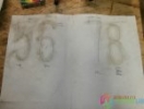
0.3 mm tungsten wires are inserted into the jig and are passed through a torch 2-4 and a reducing flame to form a gray oxidation layer. The wires will turn red for a short time (fraction of a second), this must not be done any longer, otherwise a yellow coating will be formed and this would be bad. This layer is then bonded to the glass to form a perfectly tight seal. As a result, in sealed glass, the wires have a deep, deep black color without bubbles, and that is the right look for vacuum sealing. Attached are photos of bad meals (photo 11) and good meals (photo 12).
After this operation, a chilled glass preform and a pump tube are placed in the jig and may begin to heat up.
Heating is done by burner 6-9 and reducing flame. When the glass begins to glow red-yellow, I squeeze the blank with the lever and the wires and the pump tube are sealed in the glass, then heat up the pump tube and graphite rod section with the tip to pierce the glass. I remove the semi-finished product from the jig and place it in the furnace (I put two of these seals into the furnace) on a sheet of metal so that the seal does not move and the pump tube does not bend during cooling.
After cooling the vacuum seal with a wire squeeze, I poke a hole in the pump tube, which was roughly prepared in the fixture using a graphite rod, it goes easily. Then I look at the color of the seal and if the wires in the glass have a deep blackish color and there are no bubbles along them, the seal is fine and 100% certain that it will be perfectly vacuum tight. Finally, using a polarizing foil, I check that this part is properly cooled, if it was poorly cooled, it must be able to cool again, otherwise this part would break during final welding with the flask. The description and procedure of the stress control is described in detail in Part 2. Tension control is always carried out for each workpiece taken out of the furnace and at the finished and melted digitron to give complete assurance that the product will not crack and fall apart due to temperature changes.
- Plavec-Part11_1
- Author: No Data
- Hits: 1567
- Downloads: 519
- Rating: No Votes
- Plavec-Part11_2
- Author: No Data
- Hits: 1527
- Downloads: 544
- Rating: 5.00 (1 Vote)
- Plavec-Part11_3
- Author: No Data
- Hits: 1536
- Downloads: 535
- Rating: No Votes
- Plavec-Part11_4
- Author: No Data
- Hits: 1553
- Downloads: 530
- Rating: No Votes
Part 12 * Production of internal digitron system.
The materials used to manufacture the internal digitron system are described in Part 10 and will not be re-introduced here.
I produce everything with 20 pieces, which means that I will prepare 20 sets of components from everything and then complete it in one unit.
I bend the numbers manually from the wire according to the pattern, which I cut and straighten the wire on a flat surface using a straight wooden prism. When I have 20 sets of numerals, I start to make numeral holders out of sheet metal, which I use to dial numerals in the centering tool.
After this operation, I draw the shape of the anode cage on a metal sheet on a metal sheet and manually cut and bend 20 sets. The wire cage of numerals and insulators is then pierced into this cage.
Then I cut the anode grid from the wire mesh and bend it to the desired shape, also in 20 sets.
I do not use a drill but a handheld punch to make holes in the number holders, making work easier, faster and more accurate.
With all this ready, I can start assembling and final assembly. Once assembled, a complete vacuum cage is copied onto the complete assembled cage, this operation does not need any explanation.
All the above operations are clearly understandable and legible from the photographs. I don't use rubber gloves to make these parts and assemblies because I don't work with gloves and I don't even wear gloves. Gloves are not needed, as I clean the assembled assembly at the very end as a whole, thus removing all oxides from the scoring and grease from the fingers of the hand and other unwanted dirt, and the flask is automatically cleaned. For cleaning I use deionized water, formic acid and hydrogen peroxide. I put the whole assembly with the spiked vacuum seal and further with the solution of deionized water and the above mentioned ingredients, then put the vessel in an ultrasonic water purifier and read for 15 minutes at 50 degrees Celsius. Then I remove the container, remove the assembly, and then place it in clean deionized water and turn on ultrasound to rinse the remainder of the previous solution, the assembly is completely degreased and free from scoring after this operation. This procedure also cleans glass flasks. In addition, if the system is immediately sealed into the flask, it is necessary to dry everything, using a hot air oven. I do not own this oven (but it is planned) and I dry spontaneously so far, I put some sets on clean paper and cover with paper again, everything is dry the next day. If the undried assembly starts welding with the bulb, it will dew from the inside and prevent proper glass heating and the bulb or socket will break. For 5 liters of deionized water I give 1dcl of formic acid and 1dcl of hydrogen peroxide, this solution can withstand several cleanings. The concentration of ingredients used is evident from the photographs. Just before welding the flask assembly to the top of the anode cage, I get a getter, put the whole in the flask and in another special fixture for this operation, which will be described in the next section.
- Plavec-Part12_1
- Author: No Data
- Hits: 1541
- Downloads: 538
- Rating: No Votes
- Plavec-Part12_2
- Author: No Data
- Hits: 1604
- Downloads: 565
- Rating: No Votes
- Plavec-Part12_3
- Author: No Data
- Hits: 1551
- Downloads: 539
- Rating: No Votes
- Plavec-Part12_4
- Author: No Data
- Hits: 1607
- Downloads: 544
- Rating: No Votes
part 13 * What you need to know when designing your own digitron.
You must have noticed that there is no numerical cathode assembly for digitrons, and that the numerals are installed in the cage by a jump. This is due to the fact that the shape of the numerals and subsequent mounting in the cage does not significantly obscure parts of the numerals and thus poor readability.
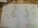
In my digitron JP47, I set out on my own geometry and sequence of digits sequentially from the bottom to the anode grid, with the numeral 0 at the top and the numeral 1 at the bottom. and the numeral 1 has a height of 135 mm. Thus, there is an ascending graduation from the smallest height to the smallest number 0 from the numeral 1. Thus I have achieved a satisfactory geometric design that does not overlap significantly, the numerals are readable in their entirety.
Furthermore, in my digitron I did not use the letter I for the number 1. I wanted to differentiate myself and insert the true Arabic number 1 into the digitron. This is my original solution, which no one has used in advance. My digitrons will always be with headphone 1.
Further to the design of the cathodes, it is important that the length difference of the unwound cathode wire is at most 50% when using a wire of the same diameter on all numerals. This is because the electrical parameters of all characters are similar and if possible identical and to be within a tolerance of max. 5mA for such a large digitron. The maximum length difference of the cathode unwound wire is 200 mm for JP47, the longest wire is 8 (380 mm) and the shortest wire is 1 and 7 (both 200 mm).
In the case of the production of numerals by etching from sheet metal, this can be precisely achieved by varying the width of the character lines. In the design of the numerals, it will already be envisaged that the front surface of each feature has the same surface as possible, thus achieving the same electrical parameters. However, this solution is not absolutely necessary, and the numerals of a small digitron can also be made of wire, because the numerals of a small digitron are smaller and thus the difference in electrical parameters will not be as high as that of a large digitron.
In addition to numerals, you can insert any 2D or 3D set of characters into digitron, the shape is not limited, it depends only on your imagination. In the case of only one cathode does not have to deal with the length and area of the emblem, it will be a one-off original matter for which the electrical parameters do not play a role. In the case of multiple cathodes, it is necessary to observe the above rule to avoid significant difference in currents on the switching elements of the control circuits when designing the electronic cathode switching.
In addition, an additional anode grid was used in some digitrons, and the Rodan CD47 digitron is an illustrative example. Rodan has an anode cage phosphate black due to glow discharge reflections and therefore an additional anode grid had to be inserted between the cathodes (roughly halfway through the assembly), because oxidation and electrical nonconductivity of the cage would not trigger the glow discharge anode cages. Thus, the additional grid applies to characters from half to anode cage. There is no additional grid in the JP47 digitron because the cage is silvery pure and conductive and the features work in their entirety. Glare from the silver cage is absolutely convenient and does not interfere with the legibility of the numbers.
There is no mica used in JP47 to center and hold the anode cage in the flask, I used my own and original method based on the principle of thrust plates. Mica is expensive and its preparation before it can be used is time and energy consuming. Mica contains about 18% of crystalline water in layers and a large amount of absorbed gases and water vapor. The mica must therefore be annealed at 500 degrees Celsius for 12 hours before use. The mica prepared in this way must be quickly consumed or stored under vacuum, otherwise it will quickly absorb everything that has been removed from it by the previous operation. Raw mica can not be used in vacuum tubes or digitron, I know of products that use mica without ignition and it is their thing, but once they do it reverses when the getter is saturated and will not be able to absorb impurities from mica, which is gradually released.
I thank all the readers of this series for their patience while waiting for the next episodes and for their positive reactions.
Part 14 * Degreasing the digitron system and building the digitron system with the socket and flask.
This time I used experimentally HCL and 35% hydrogen peroxide with deionized water. I needed to try to confuse the anode cage because of the glare from the discharge. For 1 liter of deionized water, I put 0.05 liters of technical HCl and 0.05 liters of 35% hydrogen peroxide, poured the solution into a flask with the digitron system in place, and placed the flask in ultrasonic into heated deionized water at 60 degrees Celsius and left for 5 minutes work. After removal, I rinsed in clean deionized water and then dried in a hot air oven at 75 degrees Celsius. The effect of confusion and degreasing is perfectly satisfying and fulfilled my expectations. Another possibility of degreasing with other additives is described in section 12. Photodocumentation of the cleaning process is not necessary, everything is clear from the description.
After drying I put the flask with the digitron system and the spiked base into the adjusting fixture and vacuum welded everything together. There is no need to describe the digitron base point scoring, it is a simple and hassle-free operation, tungsten scales seamlessly on stainless steel and it goes perfectly, you need to use a short time, a fraction of a second and a high current. After impregnation the tungsten is fragile around the weld and it is necessary not to move the impregnated tungsten wire, otherwise it will burst at the weld and must be scored again. When welding, therefore, score tungsten on the stainless steel cathode terminals at the end of the length, after breaking I have a reserve of length for repair, so I recommend leaving a tungsten wire reserve. Breaking tungsten happened to me only once and if you do everything calmly and prudently, nothing happens.
After welding while still hot, the unit immediately goes to the pump, but this will be described in the next part.
- Plavec-Part14_1
- Author: No Data
- Hits: 1259
- Downloads: 513
- Rating: No Votes
- Plavec-Part14_2
- Author: No Data
- Hits: 1263
- Downloads: 512
- Rating: No Votes
- Plavec-Part14_3
- Author: No Data
- Hits: 1290
- Downloads: 532
- Rating: No Votes
- Plavec-Part14_4
- Author: No Data
- Hits: 1300
- Downloads: 545
- Rating: No Votes
- Details
I came across this interesting video a while back, but didn't get around to writing anything about it at the time. It's from a chap called Mario Rigogliosi, who lives in the same town as I do, who has a real passion for restoring old equipment.
Have you ever asked yourself "what made Nixie clocks go before microcontrollers were invented"? If you did, I suppose you came to the conclusion that it was switches, levers, relays and stuff". Well, here's a look into that "stuff", and it's pretty interesting. What is written below is based on my best guesses, I'll reach out to Mario and get feedback from him.
The time source
First of all, the time source comes from the frequency of the mains supply voltage, which is a surprisingly good source of time: supply companies in all but the most dark and backward countries in the world actively manage the number of cycles delivered to the consumer very tightly, even regulated by law in some countries. For example, the supply in the UK can be seen here: http://www.dynamicdemand.co.uk/grid.htm, and on the dial you can see markers for the "Legal Limit" of deviation, over which the supplier is subject to sanctions.
The counters
The videos
- Details
Recently on the Facebook Nixie Clocks Fan Page, Peter asked if anyone had a design for a Z1000 tube mounting board. I did something for a friend who had a box of Z1000 tubes, and didn't have the possibility to design boards himself.
Here is the KiCad archive (design files and Gerbers, in the "CAM" directory):
ZM1000 6 digit display board, without separators
Search